
Phase tracker for linearly modulated signal

a linear modulation and phase tracker technology, applied in the field of digital communication, can solve the problems of limiting the link error rate performance, unable to achieve the benefit of the fec code's improved performance, and limited phase shift to two quadrants, so as to improve the phase jitter and phase slip rate performance

Inactive Publication Date: 2006-11-14
2201028 ONTARIO
View PDF11 Cites 17 Cited by
  • Summary
  • Abstract
  • Description
  • Claims
  • Application Information

AI Technical Summary

Benefits of technology

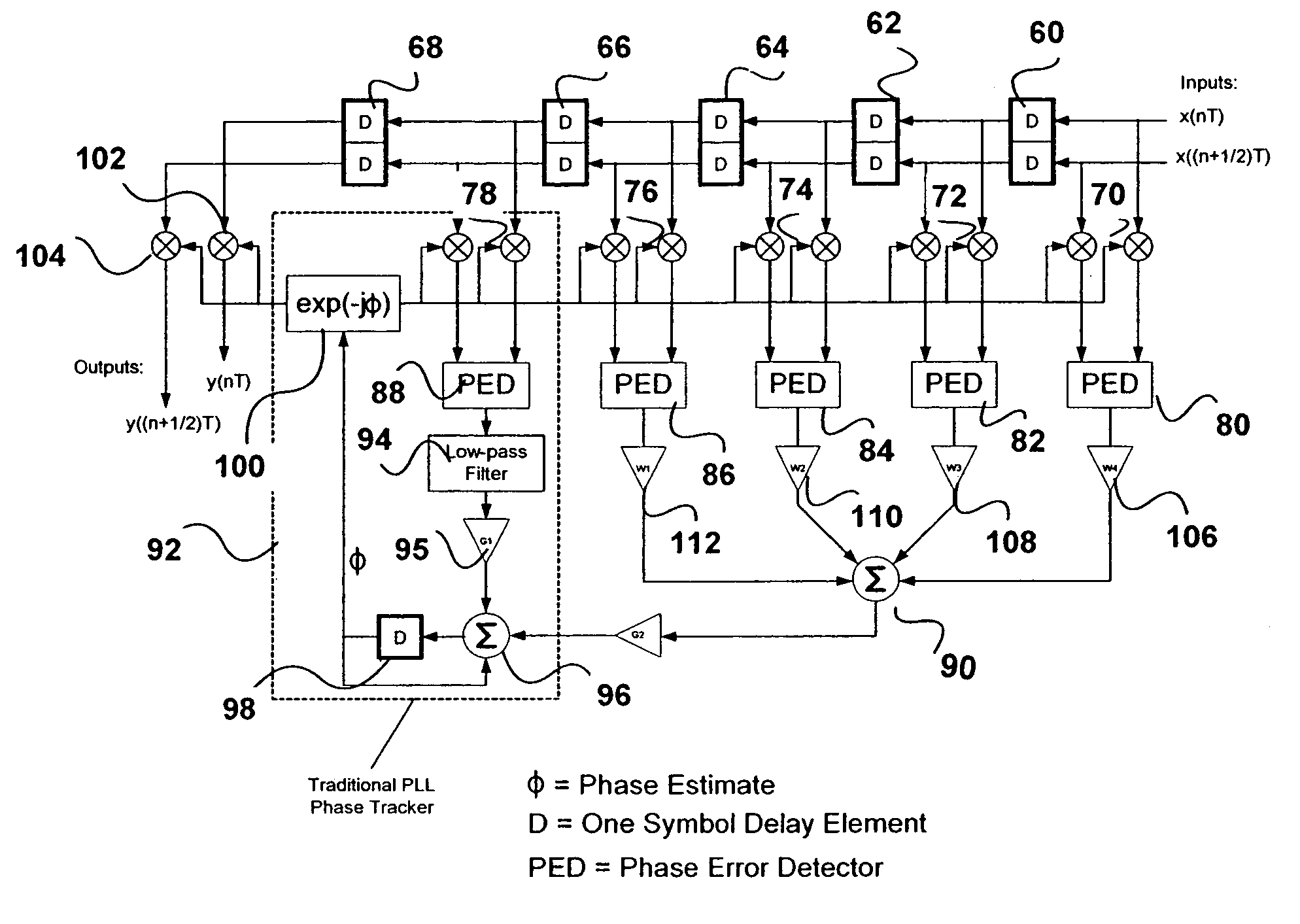
[0016]The present invention is an improvement of standard phase tracking methods which achieves improved phase jitter and phase slip rate performance under high phase noise or mobile channel conditions.
[0021]A novel aspect of the invention is that it takes into account the computed phase errors of “future” symbols. Since obviously, the invention cannot look into the future, in practice this means that a sequence of N+1 symbols are stored in a delay line, and the “current symbol” being processed is always several symbols behind the symbol actually being input to the phase tracker at any point in time. By basing the phase estimate of the current symbol in part on the phase errors of the next N future symbols, improved accuracy can be achieved at very low signal-to-noise ratios.

Problems solved by technology

Unfortunately, the phase shift is limited to two quadrants; a phase shift of π / 2 cannot be distinguished from a phase shift of −π / 2.
Otherwise, the phase tracker can become the limiting factor for the link error rate performance, and the benefit of the FEC codes' improved performance cannot be achieved.

Method used


Image

  • Phase tracker for linearly modulated signal
  • Phase tracker for linearly modulated signal
  • Phase tracker for linearly modulated signal

Examples


Embodiment Construction

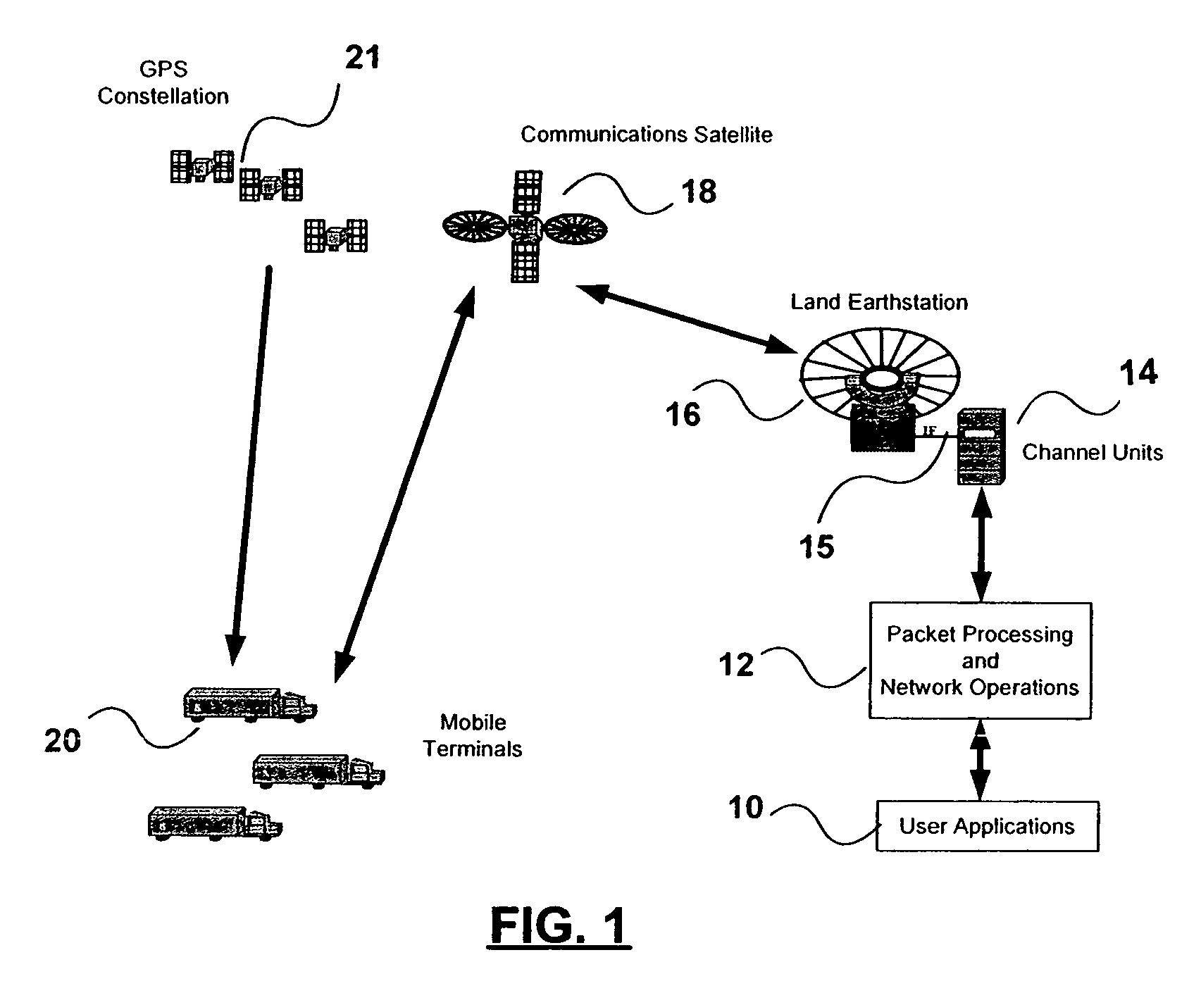
[0039]The satellite digital communications system shown in FIG. 1 is a typical application for the present invention. It could be, for example, the Globalwave™ asset tracking system. User applications 10 communicate with mobile terminals in trucks 20 via a communications satellite 18 in a geosynchronous orbit. Typically, the user applications, which could be web browser based, send text messages that are passed to the packet processing and network operations center 12, where they are processed and pass to channel units 14. These prepare a phase modulated intermediate frequency signal 15 that is passed to earthstation 16 for transmission over RF link to the satellite 18 for relay back to the mobile terminals in the trucks 20.

[0040]The mobile terminals in the trucks 20 also receive positioning signals from GPS satellites 21. This information is transmitted by to the earthstation 16 to permit the user to know the whereabouts of the trucks 20.

[0041]The data is encapsulated in packets th...


PUM


Abstract

A method is disclosed for tracking the phase of a received phase-modulated carrier carrying a sequence of symbols represented by phase jumps in a low signal-to-noise ratio environment. An input sequence of symbols stored in a delay line. The phase of a current symbol in a phase locked loop, and the phase error detected in the phase locked loop is updated to take into account phase error estimates of future symbols.

Description

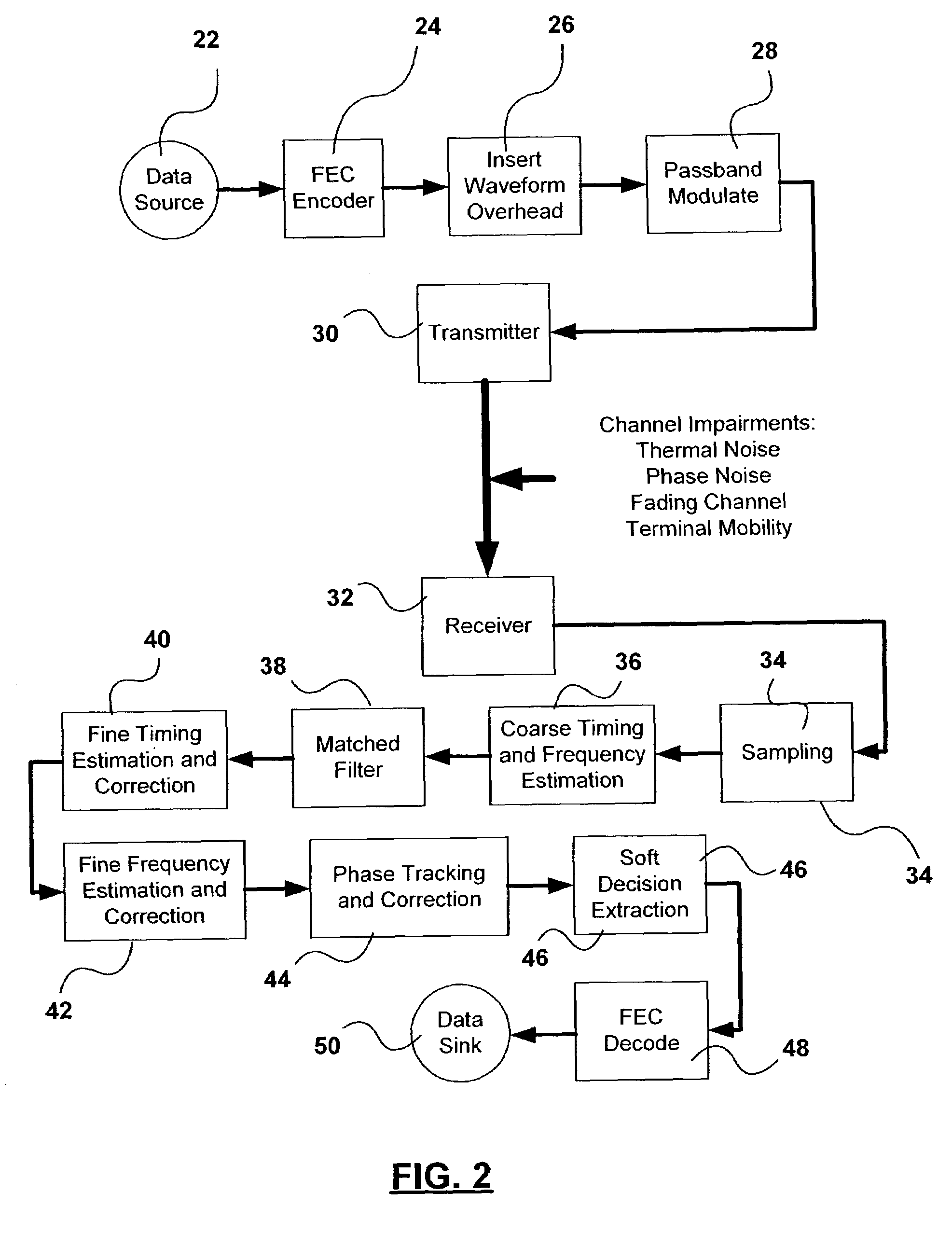
CROSS REFERENCE TO RELATED APPLICATIONS[0001]This application claims the benefit under 35 USC 119(2) of U.S. Provisional Application No. 60 / 306,165 filed Jul. 19, 2001, incorporated by reference herein.BACKGROUND OF THE INVENTION[0002]1. Field of the Invention[0003]This invention relates to the field of digital communications, and in particular to a method and apparatus for tracking the phase of a received linearly-modulated signal.[0004]2. Description of Related Art[0005]In a typical digital communications system, digital modulation techniques, such as phase modulation techniques, are used to transmit data using an analog waveform. This waveform is typically an RF carrier, but such techniques are also used in wireline systems.[0006]The data is usually modulated onto the carrier using a digital phase modulation. A simple form of digital phase modulation is phase-shift keying (PSK). This involves changing the phase of the transmitted waveform. These finite phase changes represent dig...

Claims


Application Information

Patent Timeline
IPC IPC(8): H03D3/24H03M7/40H03M7/42H03M13/35H04B7/185H04L1/00H04L27/00H04L27/233
CPCH03M7/40H03M7/42H03M13/35H03M13/6312H04B7/18513H04L1/0001H04L1/0013H04L1/0015H04L1/0026H04L27/2332H04L2027/003H04L2027/0046H04L2027/0067
Inventor HOUTMAN, TOM
Owner 2201028 ONTARIO
Learn More