Noise reducing apparatus and noise reducing method

a noise reduction and noise reduction technology, applied in the field of noise reduction apparatus, can solve the problems of encoding noise, image quality degradation more or less, and the quality of the material image itself is degraded, so as to reduce the noise of image data encoding, reduce the noise of noise reduction characteristics, and control the effect of noise reduction

Inactive Publication Date: 2006-11-14
AGILENT TECH INC +1
View PDF34 Cites 33 Cited by
  • Summary
  • Abstract
  • Description
  • Claims
  • Application Information

AI Technical Summary

Benefits of technology

[0036]According to this noise reducing apparatus, both appropriate noise reduction characteristics according to the scale factor and appropriate noise reduction characteristics according to the degree of motion can be easily implemented.
[0037]According to a second aspect of the present invention, a noise reducing method includes: at least one step of reducing encoding noise of image data with controlled noise reduction char...

Problems solved by technology

The random noise results from degraded quality of a material image itself to be encoded by an encoder.
The encoding noise is generated by, e.g., quantization error caused upon encoding.
Since the noise reducing process is a process that damages the original image in a sense, it involves degradation in image quality more or less.
Conventionally, however, since the noise reducing process and the scaling process are independent processes having completely different purposes from each other, the balance between the respective influences of the processes has not been considered particularly.
This may result in failing to obtain a sufficient noise reducing effect or may result in degraded image quality (other than noise) when the image data is subjected to such a noise reducing process and scaling process.
In other ...

Method used


Image

  • Noise reducing apparatus and noise reducing method
  • Noise reducing apparatus and noise reducing method
  • Noise reducing apparatus and noise reducing method

Examples


first embodiment

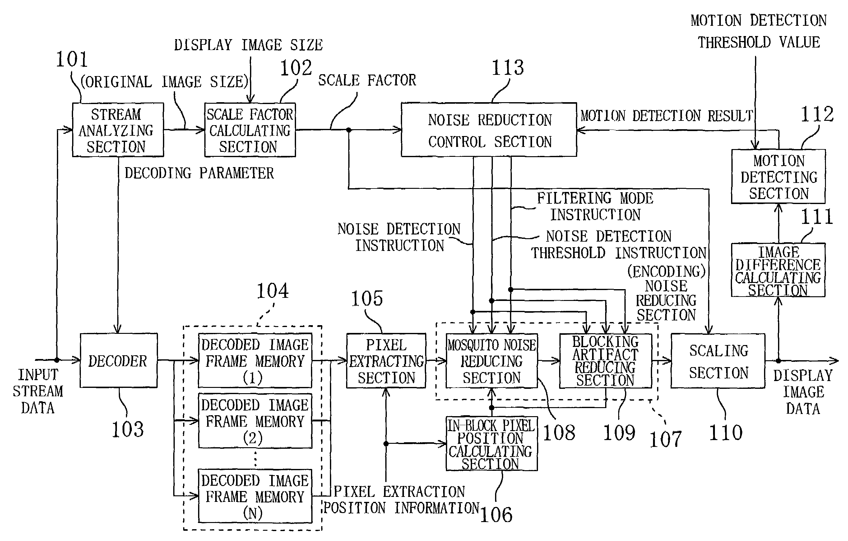
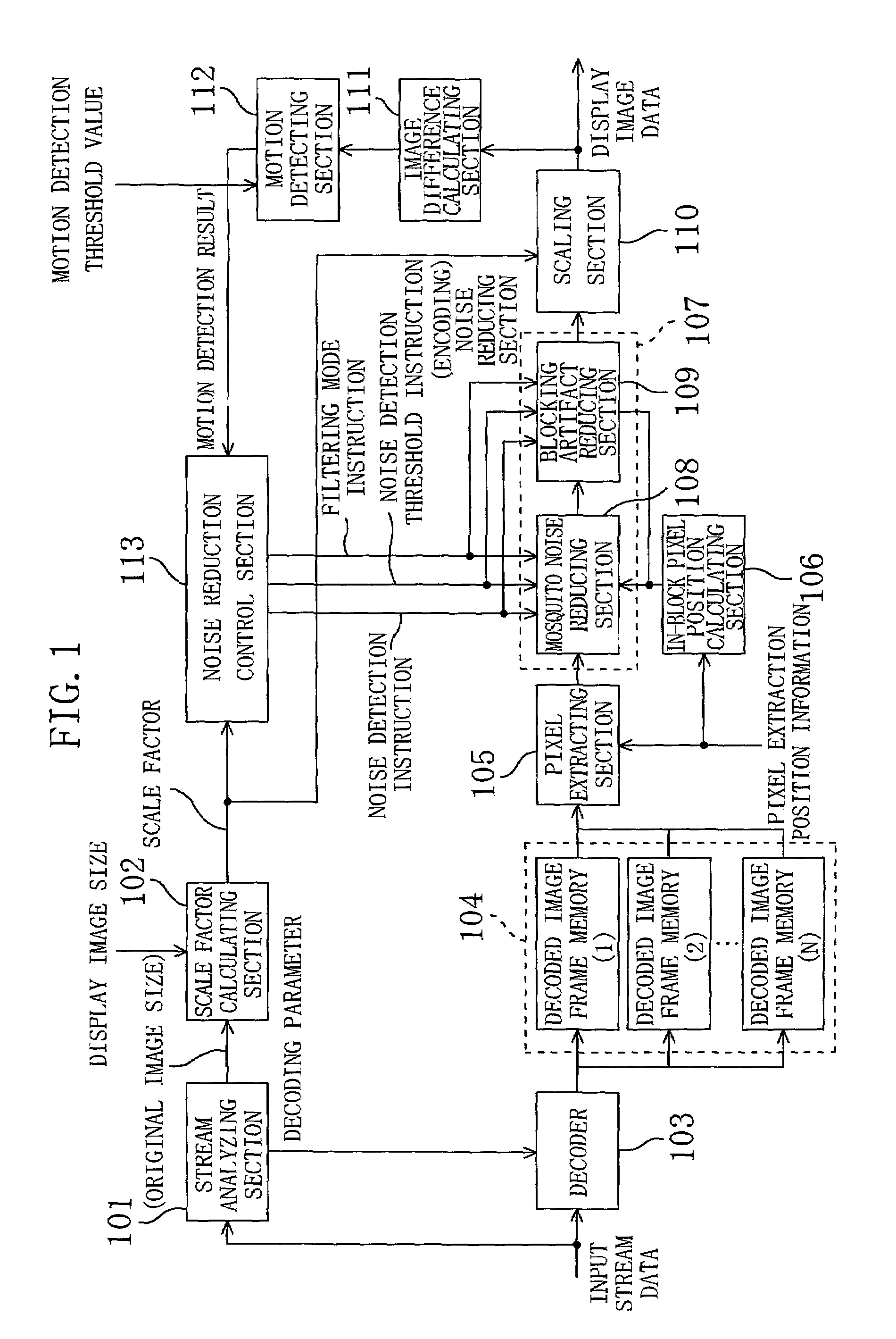
[0047]FIG. 1 is a block diagram showing the structure of a noise reducing apparatus according to the first embodiment of the present invention. In FIG. 1, a stream analyzing section 101 analyzes input stream data (i.e., encoded image data), and outputs a decoding parameter required for decoding. Based on the stream data, the stream analyzing section 101 obtains image size (original image size) for output.

[0048]A scale factor calculating section 102 calculates a scale factor of the image based on the original image size received from the stream analyzing section 101 and the actual display image size. The display image size may either be preset according to, e.g., a display device, or may be specified by operation of the user.

[0049]A decoder 103 decodes the input stream data based on the decoding parameter obtained by the stream analyzing section 101, and outputs the decoded image data.

[0050]A frame memory 104 (image memory) is a decoded image frame memory for holding N frames of the ...

second embodiment

[0079]The first embodiment shows the example in which the noise reduction characteristics are controlled according to both the scale factor and the degree of motion of the image. However, the present invention is not limited to this. For example, as shown in FIG. 4 or 5, the noise reduction characteristics may be controlled according to either the scale factor or the degree of motion of the image. Note that, in the following embodiments, elements having the same function as that of the first embodiment are denoted with the same reference numerals, and description thereof is omitted.

[0080]For example, as shown in FIG. 4, the noise reduction control section 113 of the first embodiment may be replaced with a noise reduction control section 213 that outputs a noise detection instruction, a noise detection threshold instruction and a filtering mode instruction based only on the scale factor output from the scale factor calculating section 102. In this case, the image difference calculati...

third embodiment

[0083]As shown in FIG. 6, the noise reducing apparatus of the third embodiment includes a noise reduction control section 413 including a noise detection parameter generating section 441, instead of the noise reduction control section 113 including the noise detection parameter generating section 141 in the first embodiment. In response to a still-state notification signal, the noise detection parameter generating section 441 makes a noise detection instruction “valid” regardless of the motion detection result, and outputs a noise detection threshold instruction for the still state (Note that, when no still-state notification signal is applied (when the still-state information signal is “invalid”), the noise reduction control section 413 operates in the same manner as that of the noise reduction control section 113). The still state herein refers to the state in which the image data held in the frame memory is repeatedly read for display. More specifically, in the still state, there...


PUM


Abstract

In order to reduce noise appropriately according to scaling factor and a degree of motion of an image and to suppress degradation in image quality resulting from the noise reduction to a negligible level, a noise reduction control section outputs a noise detection instruction, a noise detection threshold instruction and a filtering mode instruction based on a scale factor output from a scale factor calculating section and a motion detection result output from a motion detecting section. A mosquito noise reducing section and a blocking artifact reducing section in a noise reducing section adaptively conducts an appropriate noise reducing process using noise detection sensitivity and the number of filter taps and a filter coefficient of a smoothing filter according to these instructions.

Description

BACKGROUND OF THE INVENTION[0001]1. Field of the Invention[0002]The present invention generally relates to a noise reducing apparatus for reducing a noise component included in a digital video signal. More particularly, the present invention relates to reduction of a noise component included in a digital video signal obtained by compressively encoding image data on a block-by-block basis by an encoder and then decoding the resultant image data by a decoder.[0003]2. Description of the Related Art[0004]A digital video signal resulting from decoding of image data by a decoder includes random noise and encoding noise which is introduced in encoding process. The random noise results from degraded quality of a material image itself to be encoded by an encoder. The encoding noise is generated by, e.g., quantization error caused upon encoding. The encoding noise is thus specific to an encoding / decoding system.[0005]Specific examples of the encoding noise include mosquito noise and blocking ...

Claims


Application Information

Patent Timeline
IPC IPC(8): G06K9/40G06T5/00H04N7/26H04N7/36
CPCH04N19/51H04N19/80H04N19/86G06T5/002G06T2207/10016
Inventor KITAGAWA, MASAO
Owner AGILENT TECH INC
Why Eureka
Try Eureka