
Buried object locating and tracing method and system employing principal components analysis for blind signal detection

a blind signal detection and buried object technology, applied in the field of blind signal detection systems, can solve the problems of affecting the comfort and convenience of residents, messy and expensive cleanup efforts, and serious injury and property damage, and achieve the effect of removing the usual ambiguities of broadband electromagnetic emissions

Active Publication Date: 2006-11-14
SEESCAN
View PDF19 Cites 96 Cited by
  • Summary
  • Abstract
  • Description
  • Claims
  • Application Information

AI Technical Summary

Benefits of technology

This approach enables simultaneous detection and identification of multiple buried objects with improved accuracy, reducing ambiguities and the effects of operator motion, allowing for precise location and depth determination of buried utilities.

Problems solved by technology

If excavation equipment such as a backhoe hits a high voltage line or a gas line, serious injury and property damage may result.
Unintended severing of water mains and sewer lines generally leads to messy and expensive cleanup efforts.
The unintended destruction of power and data cables may seriously disrupt the comfort and convenience of residents and bring huge financial costs to business.
Some transmitters known in the art can produce several different signals at different frequencies for application to the same underground object or even to different underground objects, but a problem with these systems arises when several pipes are located in the same area and the location of all pipes is desired.
Signals transmitted by several pipes can interfere and complicate the detection process.
While Wilkison's system is advantageous for the active location of a particular buried object in the presence of “noise” that includes other signal emissions from other buried objects because of the improved signal-to-noise ratio (SNR) and other advantages of spread-spectrum signal processing, these advantages are not applicable to the related passive location problem.
Another problem with buried object locators known in the art is the signal phase relationships from a 3-axis sensor array, which are ambiguous and cannot alone facilitate assembly of the field vector components in the correct quadrant.
In the United Kingdom, for example, where passive detection of broadband emissions in the 15–24 kHz band is typically used to find buried wires, available broadband detection methods yield no clearly-defined phase, leaving unresolved ambiguities in the resulting field vector.
Another well-known portable locator problem is the convolution of any locator system operator motion with the received emission signal.
Even when tracing a buried utility line following its detection, small path deviations may cause signal phase reversals at the sensors whose axes are aligned substantially perpendicular to the local field vector.
This problem arises in some sensor coil embodiments where sensor signal sensitivity is generally proportional to the sine of the angle between the sensor coil axis and the local field vector.
Practitioners in the art have proposed no solutions for this particular disadvantageous effect of operator motion.

Method used


Image

  • Buried object locating and tracing method and system employing principal components analysis for blind signal detection
  • Buried object locating and tracing method and system employing principal components analysis for blind signal detection
  • Buried object locating and tracing method and system employing principal components analysis for blind signal detection

Examples


Embodiment Construction

Introduction

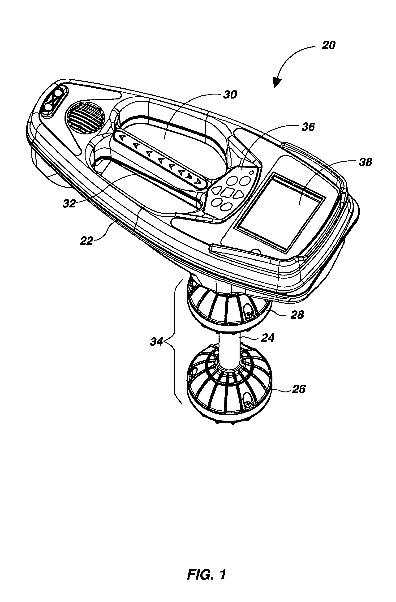
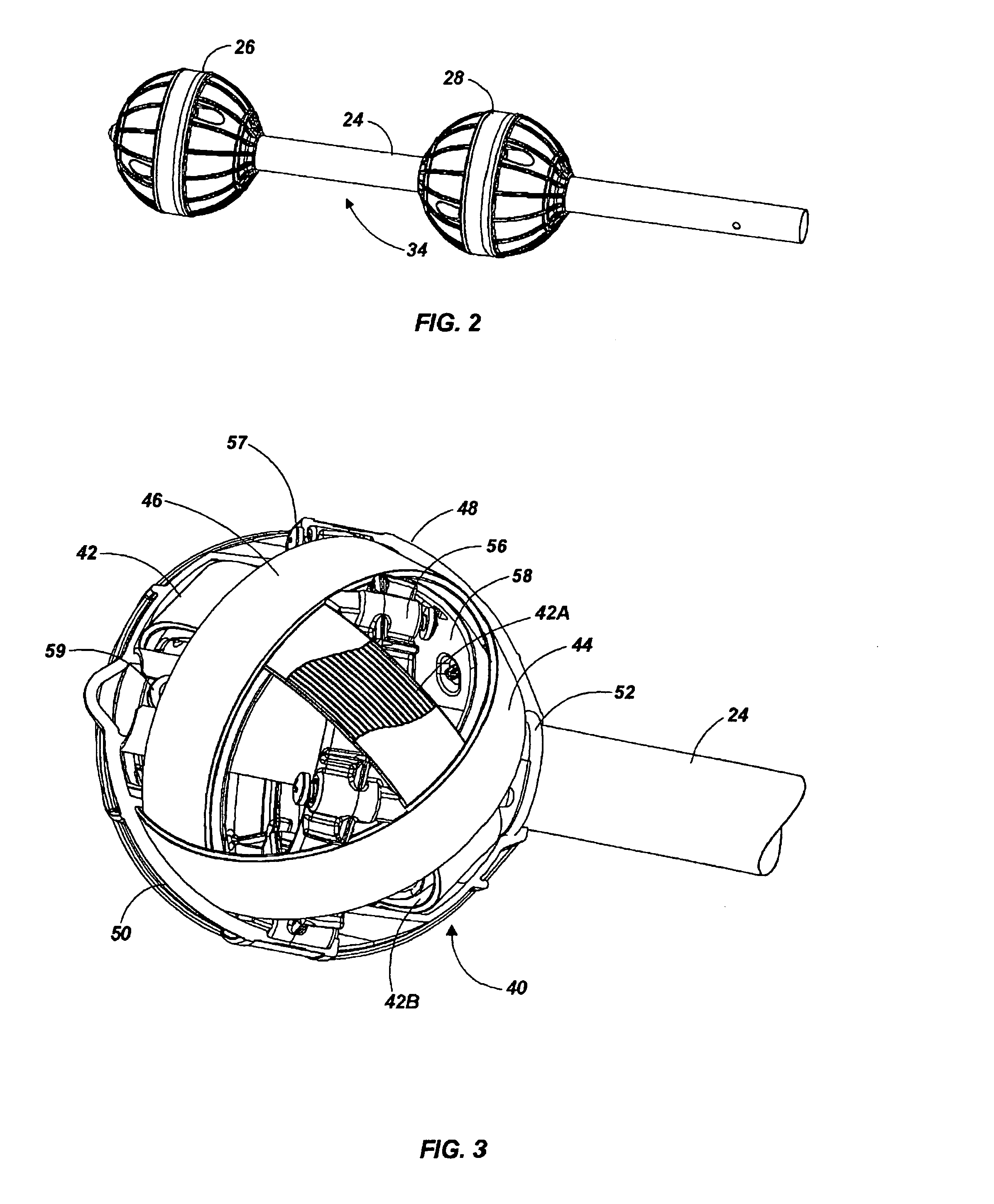
[0038]For several detailed discussions of exemplary buried object locator embodiments suitable for use with the system and method of this invention, reference is made to the above-cited commonly-assigned patent applications incorporated herein by reference. For example, FIG. 1 is a perspective view of a battery-powered omnidirectional, portable system 20 useful for locating a buried object by sensing an electromagnetic signal emitted by the buried object. System 20 includes a housing 22 and an elongate member 24 (FIG. 2) that supports spaced apart lower and upper sensor balls 26 and 28, respectively, and connects them to the housing 22. Housing 22 (FIG. 1) includes rigid plastic shells having a large central aperture 30 spanned by a handle portion 32. Lower and upper sensor balls 26 and 28 each include a plurality of electromagnetic sensors (FIG. 3) and together form a sensor assembly 34. Circuit means such as those embodiments described below in connection with FIGS. 5–...


PUM


Abstract

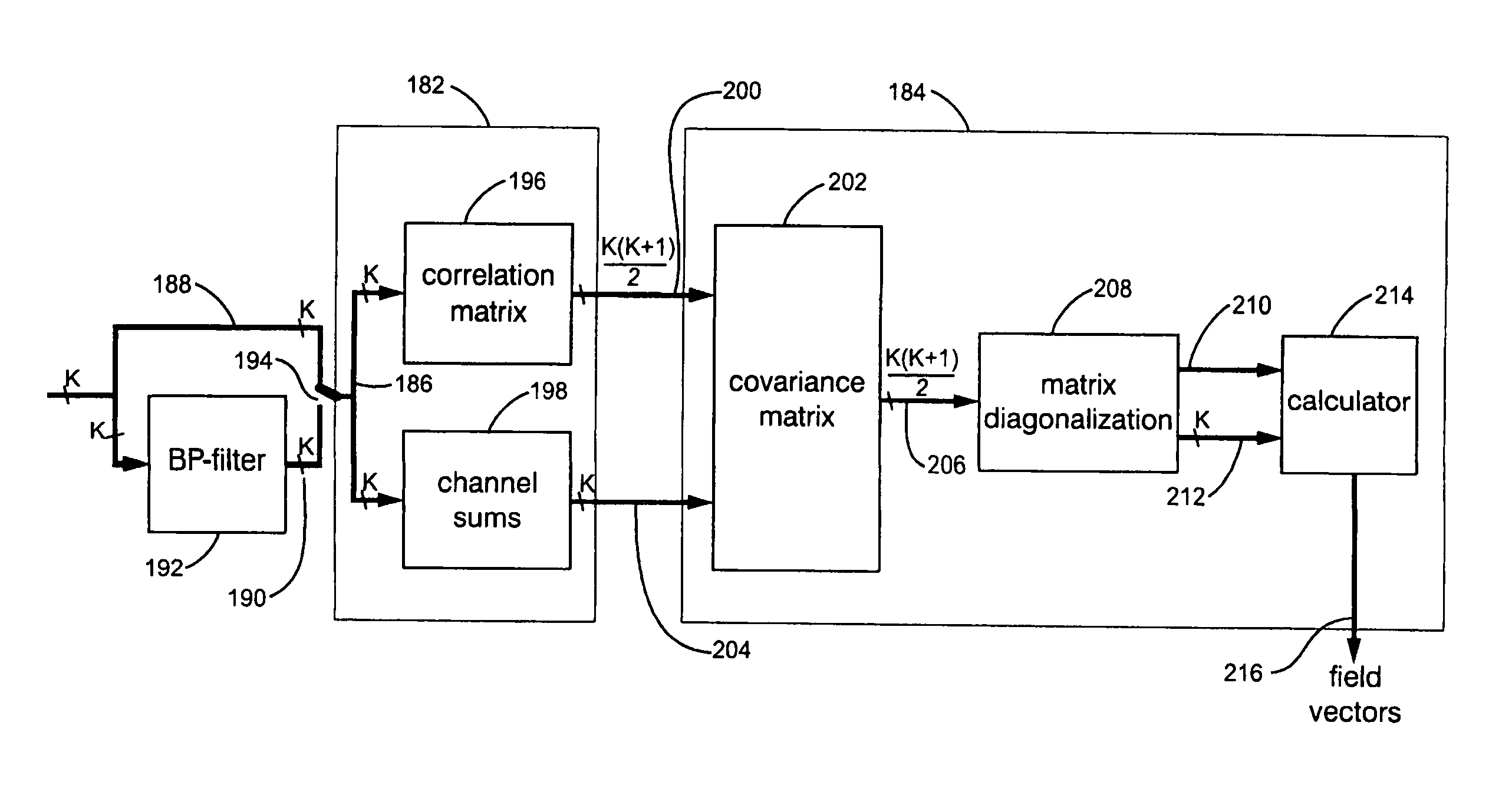
A blind locating system for finding and tracing buried objects such as utility lines, conductive pipes and sondes. A sensor array is coupled to a signal processor, which determines a field vector for one or more buried objects by producing a data signal representing a covariance matrix corresponding to the covariances of the time-varying sensor array signals over a selected frequency band and accumulation interval. The covariance matrix is characterized by eigenvalues and associated eigenvectors and a user interface (UI) indicates the field vector associated with the eigenvector having the largest eigenvalue. Using several different frequency bands, a plurality of underground objects may be simultaneously detected and indicated in the UI without foreknowledge of their existence or characteristics.

Description

CROSS-REFERENCES TO RELATED APPLICATIONS[0001]This application is related by common inventorship and subject matter to the commonly-assigned patent application Ser. No. 10 / 268,641 filed on Oct. 9, 2002, patent application Ser. No. 10 / 308,752 filed on Dec. 3, 2002, and patent application Ser. No. 10 / 956,328 filed on Oct. 1, 2004, which are all entirely incorporated herein by this reference. This application is a continuation of the commonly-assigned patent application Ser. No. 11 / 054,776 filed on Feb. 9, 2005.BACKGROUND OF THE INVENTION[0002]1. Field of the Invention[0003]This invention relates generally to systems for locating and tracing buried objects and more particularly to a system for simultaneously detecting and tracing several buried objects by means of various combinations of active and passive blind signal detection.[0004]2. Description of the Related Art[0005]There are many situations where is it desirable to locate buried utilities such as pipes and cables. For example, ...

Claims


Application Information

Patent Timeline
Patent Type & Authority Patents(United States)
IPC IPC(8): G01V3/08
CPCG01V3/12
Inventor MAIER, CHRISTOPH H.MEREWETHER, RAYOLSSON, MARK S.
Owner SEESCAN
Learn More