Drive axle for motor vehicles and method for assembling the same

a technology for driving axles and motor vehicles, applied in the direction of manufacturing tools, transportation and packaging, gearing, etc., can solve the problems of both banjo and salisbury axles having disadvantages, and achieve the effect of simplifying assembly and servicing, improving modularity of differential assembly design, and reducing the number of required machining operations

Inactive Publication Date: 2006-11-21
DANA AUTOMOTIVE SYST GRP LLC
View PDF15 Cites 12 Cited by
  • Summary
  • Abstract
  • Description
  • Claims
  • Application Information

AI Technical Summary

Benefits of technology

[0014]Therefore, the rigid drive axle assembly and the method for assembling it in accordance with the present invention represents a novel arrangement of the drive axle assembly and assembling technique providing a number of advantages over the currently employed Salisbury and Banjo style axles, such as improved strength to weight ratio, ease of manufacturing and reduced manufacturing cost due to the use of simple metal stampings to produce the support beam member and the front cover, ease of assembly / disassembly and servicing of the axle assembly, and improved modularity and commonality of axle components.

Problems solved by technology

However, both Banjo and Salisbury type axles have their disadvantages.

Method used


Image

  • Drive axle for motor vehicles and method for assembling the same
  • Drive axle for motor vehicles and method for assembling the same
  • Drive axle for motor vehicles and method for assembling the same

Examples


Embodiment Construction

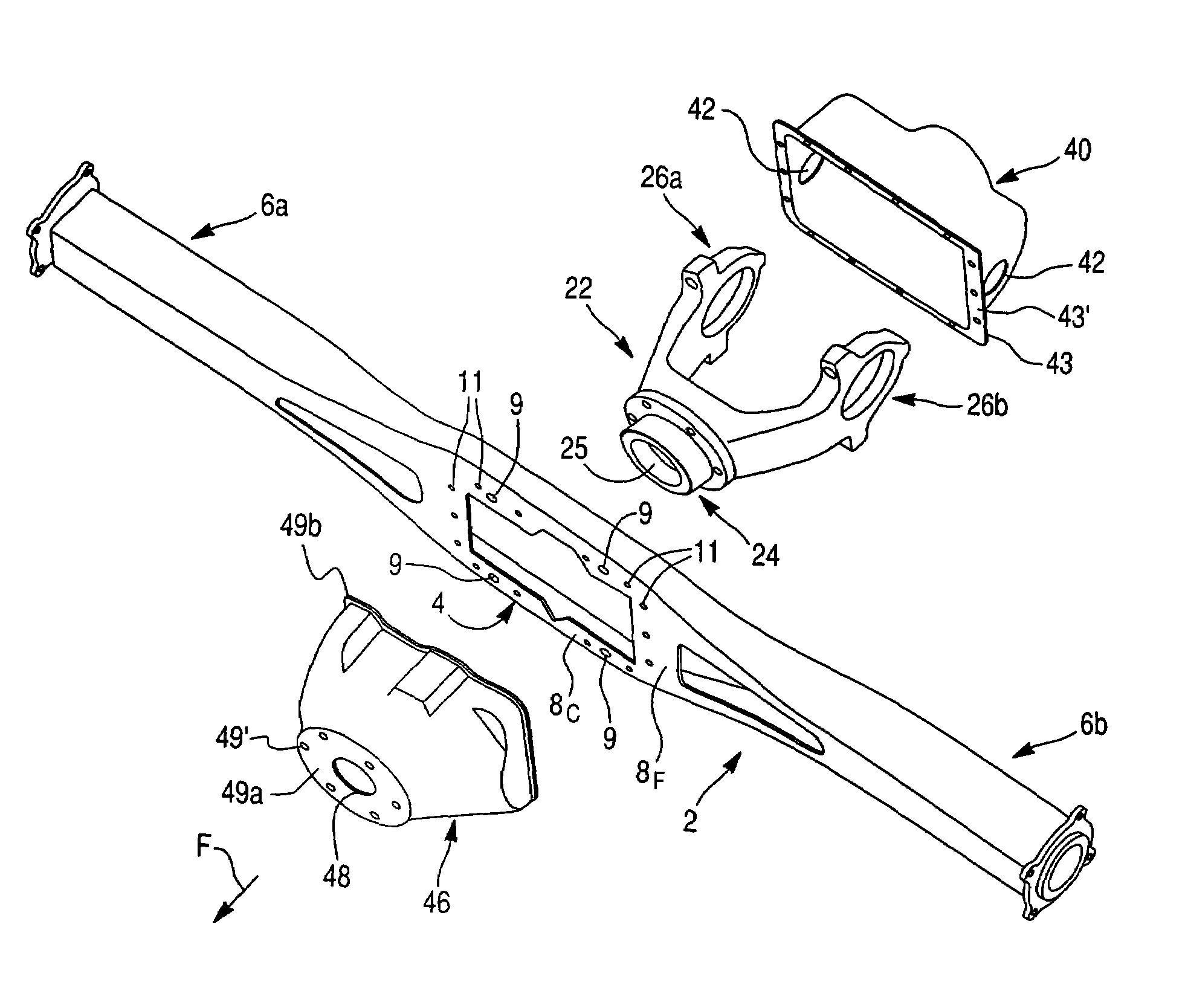
[0025]The preferred embodiment of the present invention will now be described with the reference to accompanying drawings. As used herein, the words “front” and “rear” in the following description are referred with respect to a driving direction of a motor vehicle, as indicated in the accompanying drawing figures by an arrow F.

[0026]FIGS. 3–5 depict a vehicle rigid drive axle assembly 1 in accordance with the first exemplary embodiment of the present invention. It will be appreciated that the present invention is equally applicable to an independent drive axle assembly, and may be used for both front and rear axle applications.

[0027]The rigid drive axle assembly 1 comprises a support beam member 2 having a substantially flat, enlarged central plate section 4 and two opposite, substantially tubular arm sections 6a and 6b axially outwardly extending from the central plate section 4. As illustrated, the flat central plate section 4 of the support beam member 2 is in the form of a subst...


PUM

PropertyMeasurementUnit
heightaaaaaaaaaa
structuresaaaaaaaaaa
rotational poweraaaaaaaaaa

Abstract

A drive axle assembly for motor vehicles, includes a support beam member having a substantially flat, enlarged central plate section and two opposite arm sections, a differential assembly module secured to the central plate section and enclosed into a housing formed by a rear cover and a front cover secured to opposite surfaces of the central plate section. A method for assembling the drive axle assembly comprises the steps of securing the front cover to a front mounting surface of the support beam member, fastening the differential assembly module to the central plate section of the support beam member, and fastening the rear cover to the rear mounting surface of the support beam member.

Description

CROSS-REFERENCE TO RELATED APPLICATION[0001]This Application is a continuation-in-part of U.S. Application Ser. No. 10 / 101,188, filed on Mar. 20, 2002 now U.S. Pat. No. 6,729,207.BACKGROUND OF THE INVENTION[0002]1. Field of the Invention[0003]The present invention relates to axle assemblies for motor vehicles and methods for assembling thereof in general, and more particularly to a method for assembling axle assemblies.[0004]2. Description of the Prior Art[0005]Rigid drive axle assemblies are well known structures that are in common use in most motor vehicles. Such axle assemblies include a number of components that are adapted to transmit rotational power from an engine of the motor vehicle to wheels thereof. Typically, the rigid drive axle assembly includes a hollow axle housing, a differential, which is rotatably supported within the axle housing by a non-rotating carrier. The differential is connected between an input drive shaft extending from the vehicle engine and a pair of o...

Claims


Application Information

Patent Timeline
Patent Type & Authority Patents(United States)
IPC IPC(8): F16H57/02B60B35/16B60K17/16F16H48/08
CPCB60B35/16B60K17/16B60K17/165F16H48/08F16H57/021Y10T74/2188B60B2310/206B60B2310/208B60B2310/302B60B2310/305B60B2360/10B60B2360/102B60B2380/14B60B2900/113B60G2206/014B60G2206/31F16H2048/082F16H2048/382Y10T29/49892Y10T29/4984Y10T29/49963Y10T74/2186Y10T29/49893B60B2310/202
Inventor STUART, EDWARD EUGENEALLMANDINGER, TIMOTHY BERNARDHOEFER, SEAN KARLIRWIN, EARL JAMESNANUA, PARVINDER SINGHMASER, GREGORY JAMES
Owner DANA AUTOMOTIVE SYST GRP LLC
Why Eureka
Try Eureka