Magnetically driven gear pump

a gear pump, magnetic technology, applied in the direction of gear pump, positive displacement liquid engine, liquid fuel engine, etc., can solve the problems of adding to the complexity of the structure and the necessary tolerances, and achieve the effect of simplifying the structur

Active Publication Date: 2006-11-21
PSG CALIFORNIA LLC
View PDF42 Cites 35 Cited by
  • Summary
  • Abstract
  • Description
  • Claims
  • Application Information

AI Technical Summary

Benefits of technology

[0014]Thus, the present invention presents an alternative to the longer, more complicated magnetically driven gear pumps that required an additional bracket portion of the pump housing between the magnetic drive components and the rotor gear. The present invention also simplifies the structures by utilizing an offset stationary shaft for the rotor gear and an idler gear, as opposed to having the gears rotate on two separate stationary shafts or rotate with two rotating shafts.

Problems solved by technology

Moreover, the separate rotating rotor shaft and stationary shaft for the idler gear add to the complexity of the structures and tolerances necessary to make a successful, reliable pump.

Method used


Image

  • Magnetically driven gear pump
  • Magnetically driven gear pump
  • Magnetically driven gear pump

Examples


Embodiment Construction

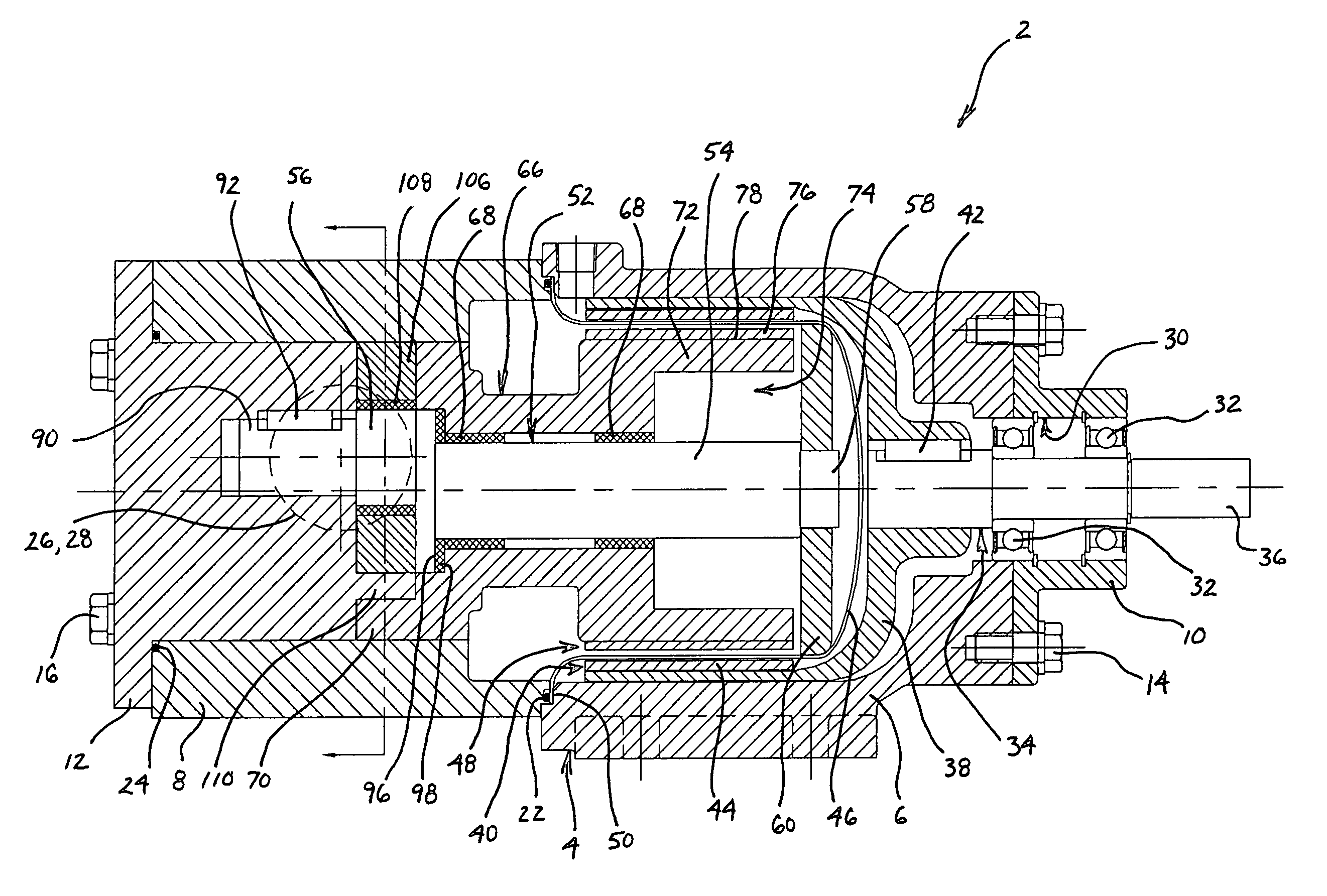
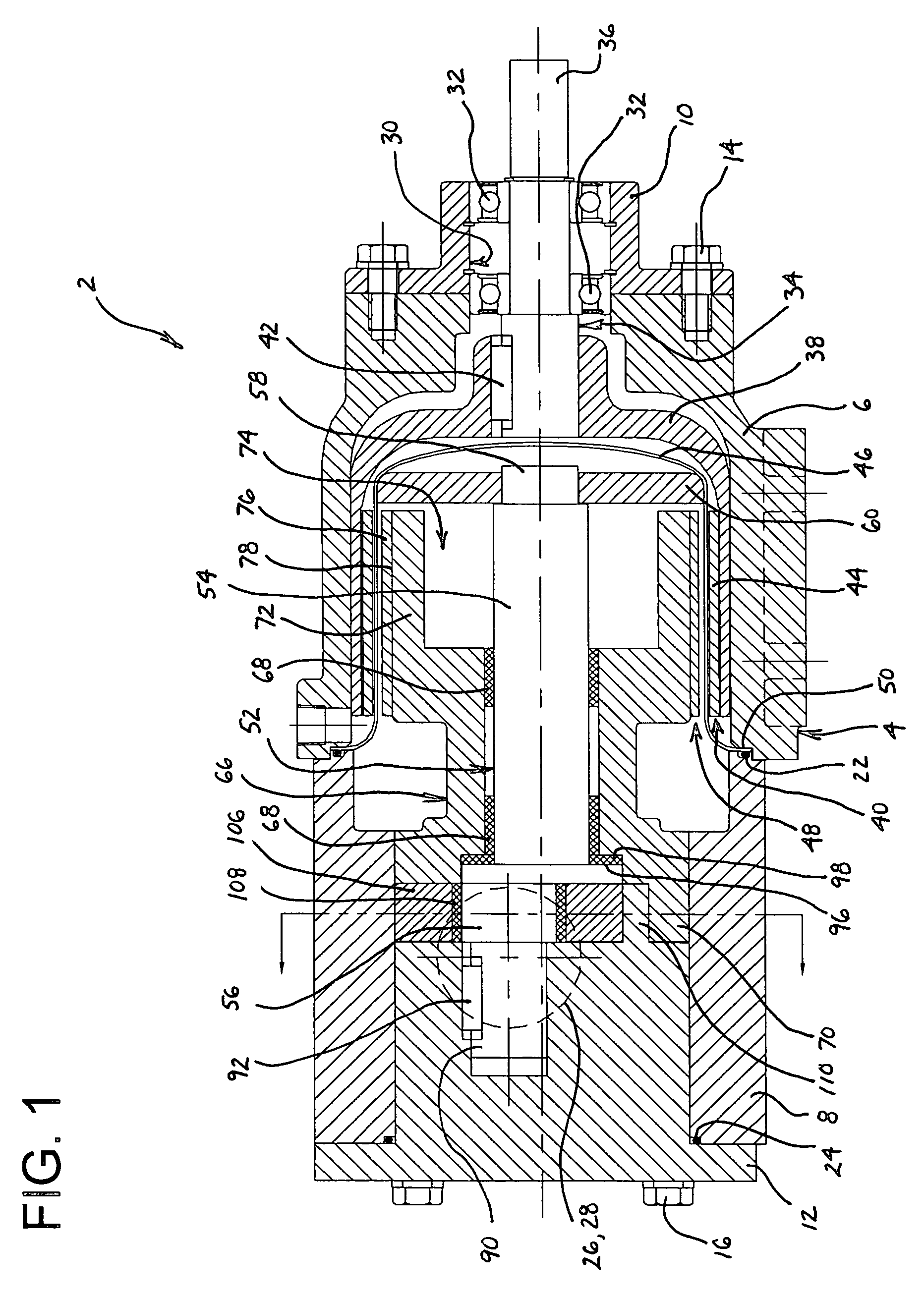
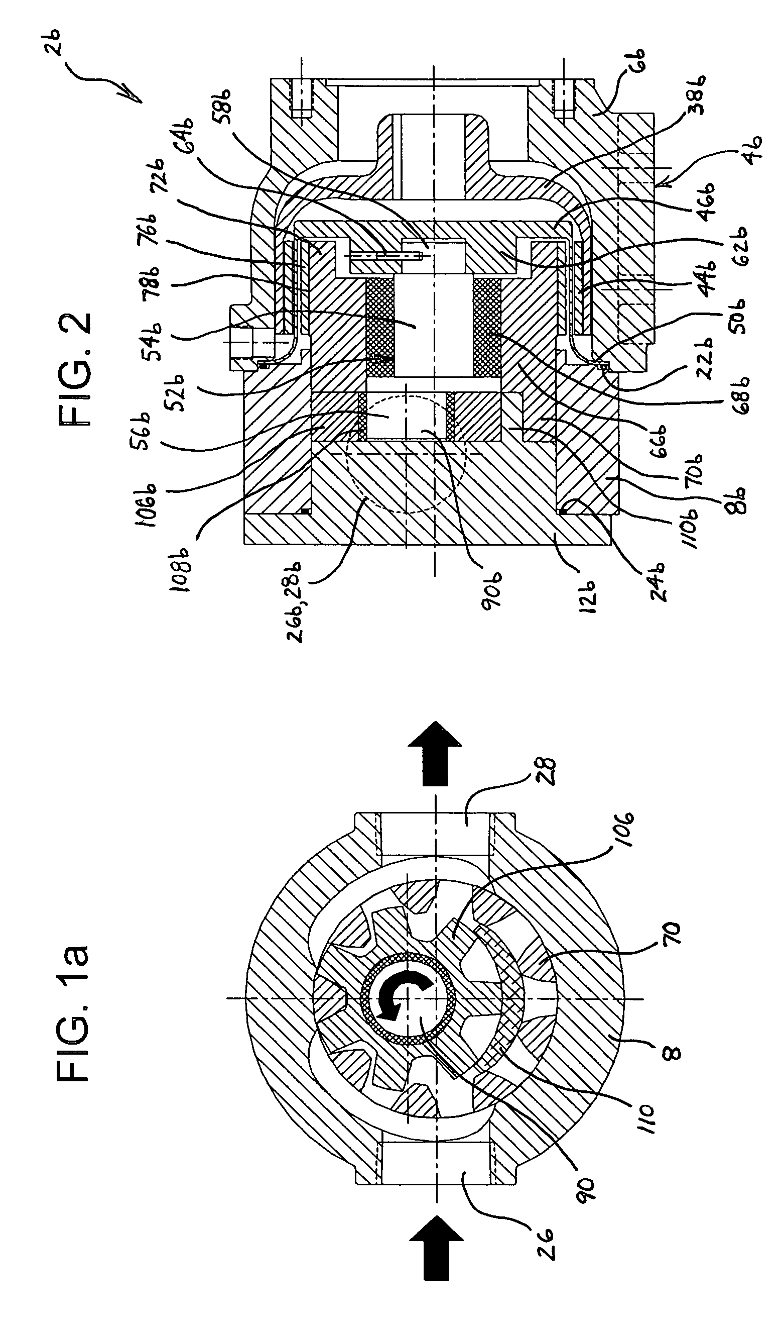
[0026]Referring generally to FIGS. 1–6a, it will be appreciated that the magnetically driven gear pump of the present invention generally may be embodied within numerous configurations of a sealless positive displacement gear pump.

[0027]Referring to a preferred embodiment in FIG. 1, a pump 2 has a housing 4 that includes a first body portion 6, a second body portion 8, a bearing cap 10 connected to the first body portion 6 and a head 12 connected to the second body portion 8. The housing components may be constructed of rigid materials, such as steel, stainless steel, cast iron or other metallic materials, or structural plastics or the like. Bearing cap 10 is connected to first body portion 6 by bolts 14, although it will be appreciated that such connection may be by other fastening means, or by direct connection of the components, such as by press fit or by threaded engagement. Alternatively, bearing cap 10 and first body portion 6 may be integrally formed as one piece. Housing hea...


PUM


Abstract

A magnetically driven gear pump having a housing, a rotatable annular magnetic drive assembly magnetically coupled to but spaced from an annular driven magnet and rotor gear assembly with an annular canister disposed therebetween, and wherein when the annular magnetic drive assembly is rotated, the annular driven magnet and rotor gear assembly rotate on a first shaft portion of an offset stationary shaft and the rotor gear drives an idler gear that rotates on a second shaft portion of the offset stationary shaft.

Description

BACKGROUND OF THE INVENTION[0001]1. Field of the Invention[0002]The present invention generally relates to positive displacement gear pumps, and more particularly to a magnetically driven gear pump of simplified construction having a magnet and rotor assembly and an offset stationary shaft on which two respective gears rotate.[0003]2. Discussion of the Prior Art[0004]In many pumping applications, it is desirable to avoid potential seal leakage by not using seals in conjunction with rotating parts. Accordingly, it has become more common in the pump arts to employ a magnetic drive system to eliminate the need for seals along rotating surfaces. While such pumps may still employ static seals, because of their lack of dynamic or rotational seals, they have become known as a “sealless” pump. Indeed, magnetic drive structures have been used in the design of positive displacement gear pumps as well.[0005]In some prior art magnetically driven gear pumps, it is common to have a driven shaft o...

Claims


Application Information

Patent Timeline
Patent Type & Authority Patents(United States)
IPC IPC(8): F04B17/00F01C1/10F16H1/06F01C1/02F01C1/063F01C1/18F01C1/24F04C2/10F04C15/00
CPCF04C2/101F04C15/0069F04C2240/60F01C1/02F01C1/063F01C1/18F01C1/24
Inventor SHAFER, CLARK J.BLANKEMEIER, WILLIAM R.
Owner PSG CALIFORNIA LLC
Why Eureka
Try Eureka