Motor control system and method of the same

a technology of motor control system and motor device, which is applied in the direction of electric variable regulation, process and machine control, instruments, etc., can solve the problems of errors in the phase will affect the control manner of the device, and usually still errors in the phase, so as to reduce the steady-state phase error of the motor device, the effect of reducing the transition time and achieving rapid steady-sta

Active Publication Date: 2006-11-21
MEDIATEK INC
View PDF16 Cites 2 Cited by
  • Summary
  • Abstract
  • Description
  • Claims
  • Application Information

AI Technical Summary

Benefits of technology

[0008]The objective of the present invention is to provide a motor control system for reducing the steady-state phase error of a motor device, so that the motor device can work under more ideal predetermined phase, and the transition time is reduced, so as to reach steady state quickly. The present invention provides a motor control system for controlling a motor device to achieve the functions of reducing steady-state phase error and transition time. The motor control system of the present invention comprises a motor controller and a compensating device. The motor controller, the compensating device, and the motor device are situated on a first feedback path, so that the motor device is controlled in the feedback manner. The motor controller is used for generating a motor control output to the compensating device according to a reference signal and a first signal fed back from the motor device. The compensating device comprises a low pass filter (LPF), a compensating offset generator, and an adder. The above three are situated on a second feedback path. The second signal generated by the compensating offset generator compensates the motor control output received by the compensating device via the second feedback path, so as to obtain a corresponding compensated motor control output.
[0010]The motor control system of the present invention utilizes the second signal generated via the second feedback path in the compensating device for estimating and compensating the motor control output to reduce the steady-state phase error. While improving the operation in steady state, the present invention utilizes appropriate initial compensating offset and adaptive manner for gradually adjusting the second signal, so that the transition time is reduced, and the problem that the motor system of the prior art needs longer time to reach steady state is improved.

Problems solved by technology

Although the motor system 10 has accurate frequency in steady state, there are still errors in the phase.
The errors in the phase will affect the control manner of a device utilizing the motor system 10.
Moreover, even if the motor device 12 reaches the steady state and has the accurate frequency, there are usually still errors in the phase.
In devices which request more accurate phase, this kind of the motor device 12 does not conform to the standard and causes problems in some devices.
According to the above description, the motor system 10 of the prior art in steady state has some problems, e.g. larger phase error and longer transition time, to be improved.

Method used


Image

  • Motor control system and method of the same
  • Motor control system and method of the same
  • Motor control system and method of the same

Examples


Embodiment Construction

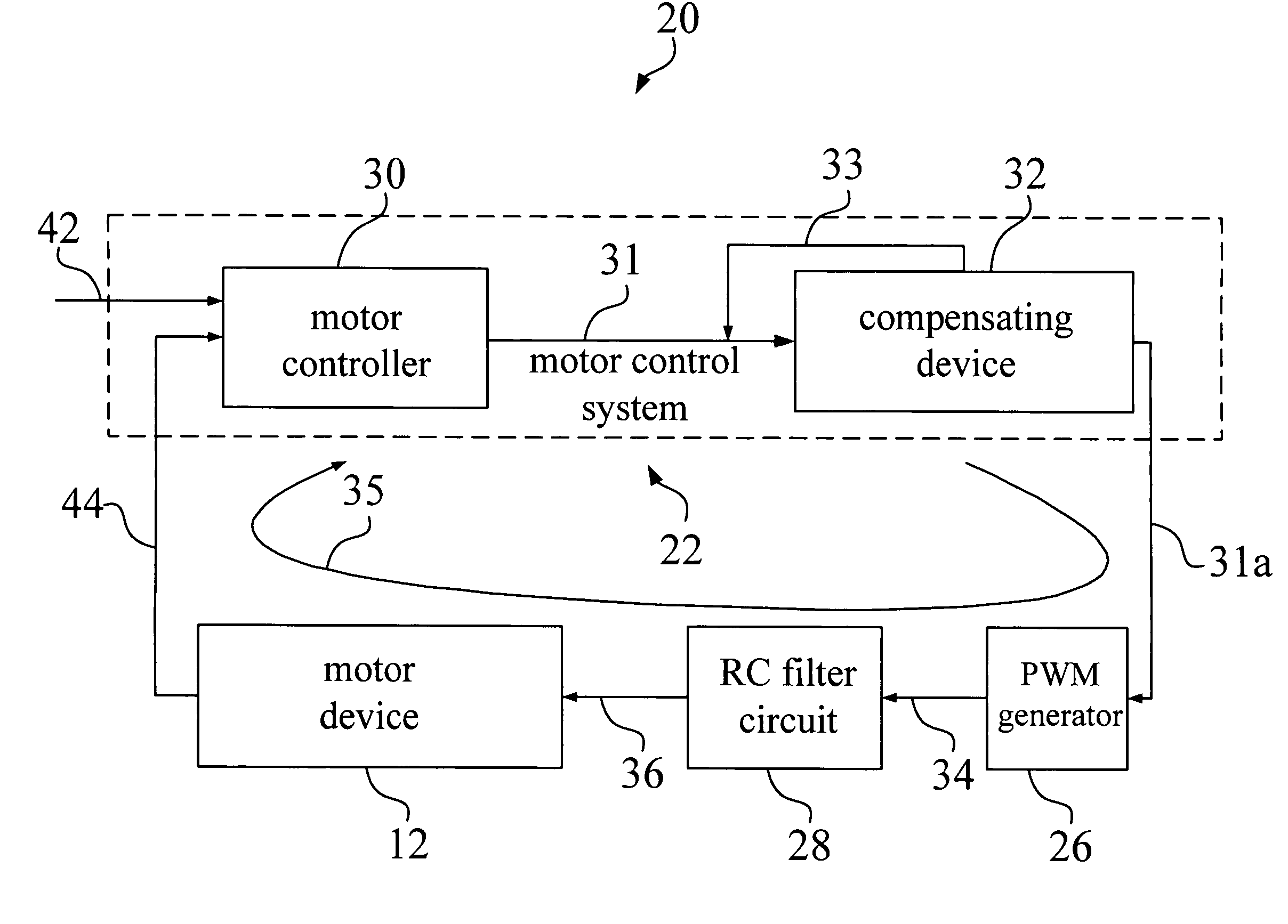
[0030]The present invention provides a motor control system for controlling a motor device to achieve the functions of reducing steady-state phase error and transition time.

[0031]Please refer to FIG. 3. FIG. 3 shows a schematic diagram of a motor control system 22 in a motor system 20 according to the present invention. According to one embodiment of the present invention, the motor system 20 comprises a motor device 12, a motor control system 22, a PWM generator 26, and an RC filter circuit 28 for forming a first feedback path 35. The motor control system 22 of the present invention comprises a motor controller 30 and a compensating device 32. As mentioned in the above description, the control signal output generated by the motor control system 22 passes through the PWM generator 26 and the RC filter circuit 28 to control the motor device 12. The motor controller 30 generates a motor control output 31 to the compensating device 32 according to a reference clock signal 42 and a firs...


PUM

PropertyMeasurementUnit
steady-state phase erroraaaaaaaaaa
control voltageaaaaaaaaaa
current angular speedaaaaaaaaaa

Abstract

The present invention provides a motor control system and method thereof. The motor control system comprises a motor controller and a compensation device. The motor controller is used for generating a motor control output according to a reference signal and a first signal. The compensation device is used for generating a compensated motor control output according to the motor control output and a second signal. Moreover, the compensation device utilizes the compensated motor control output to reduce the steady-state phase error between the first signal and the reference signal.

Description

BACKGROUND OF THE INVENTION[0001]1. Field of the Invention[0002]The present invention relates to a motor control system and method thereof, especially to a motor control system and method thereof for reducing the steady-state phase error and the transition time.[0003]2. Description of the Prior Art[0004]Please refer to FIG. 1(a), FIG. 1(b), and FIG. 1(c). FIG. 1(a) is a schematic diagram of a motor system 10 of the prior art. FIG. 1(b) is a schematic diagram of a motor controller 30 of the prior art. FIG. 1(c) is a schematic diagram of a transfer function of the motor controller 30 of the prior art. The motor system 10 of the prior art usually comprises a motor device 12, a motor controller 30, a pulse width modulation (PWM) generator 26, and a resistance-capacitance (RC) filter 28. The motor controller 30 is used for controlling the motor device 12. As shown in FIG. 1(b), the motor controller 30 comprises a frequency detector 11 and a phase detector 13. The frequency detector 11 is...

Claims


Application Information

Patent Timeline
Patent Type & Authority Patents(United States)
IPC IPC(8): G05D23/275G11B19/28H02P5/00
CPCH02P29/00G11B19/28
Inventor TSAI, CHAO-LUNGWU, CHANG-LONG
Owner MEDIATEK INC
Why Eureka
Try Eureka