
Intra-oral camera system with chair-mounted display

a camera system and camera technology, applied in the field of intraoral camera systems, can solve the problems of cumbersome process, cumbersome process, cost, etc., and achieve the effect of convenient display of captured image(s) and easy viewing and acting

Inactive Publication Date: 2006-11-21
CARESTREAM HEALTH INC
View PDF6 Cites 867 Cited by
  • Summary
  • Abstract
  • Description
  • Claims
  • Application Information

AI Technical Summary

Benefits of technology

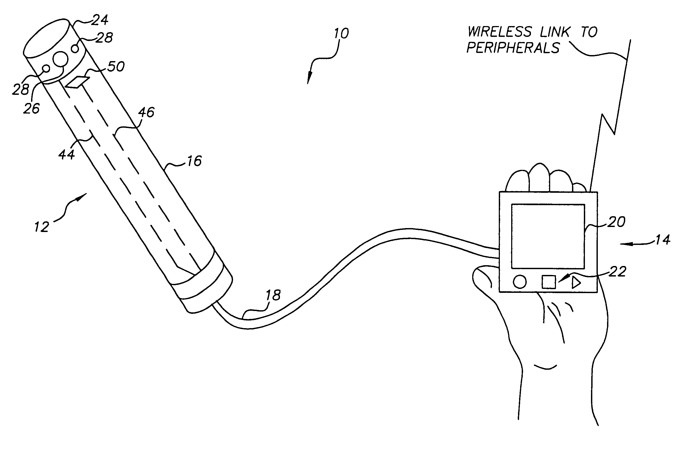
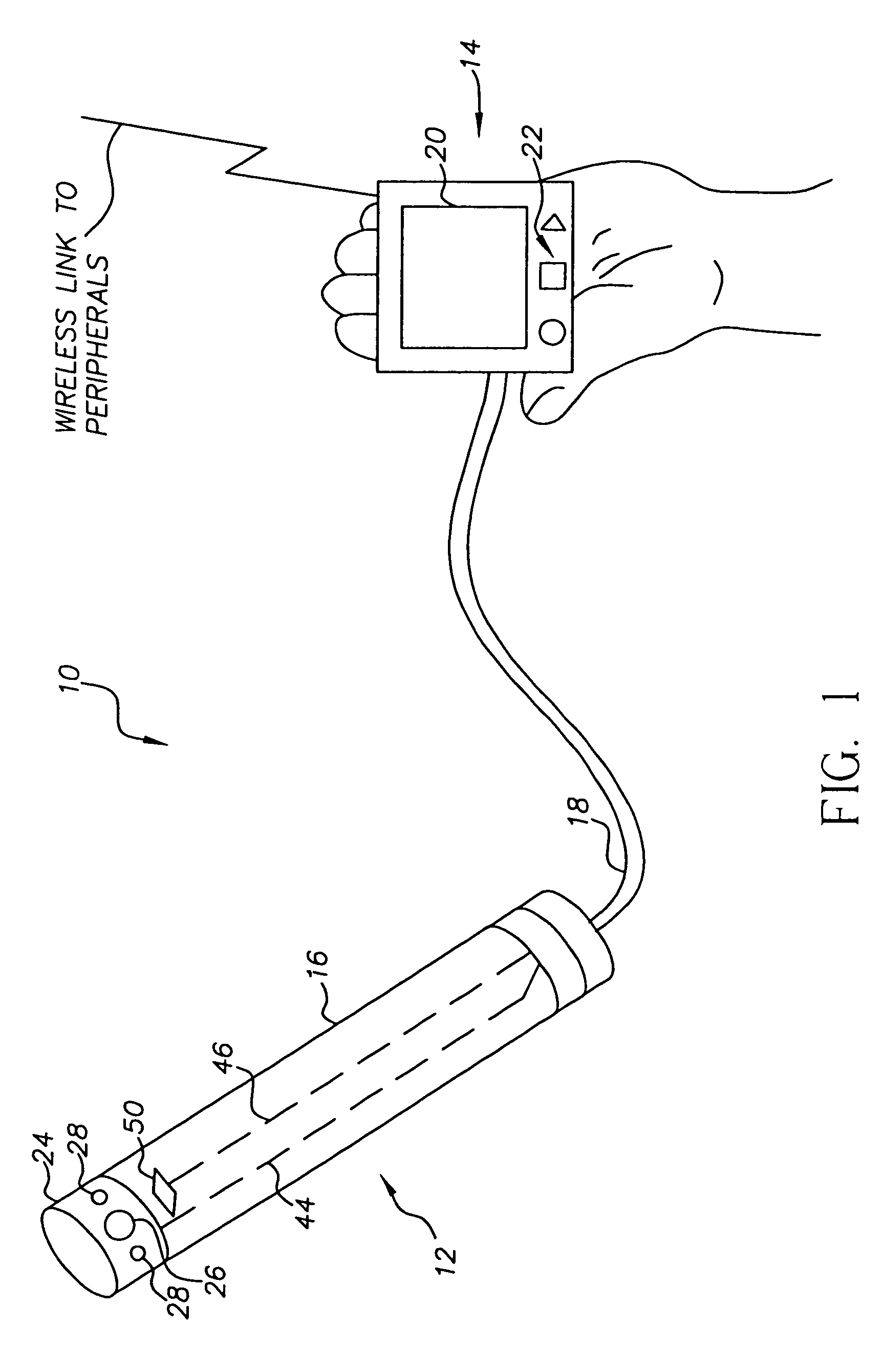
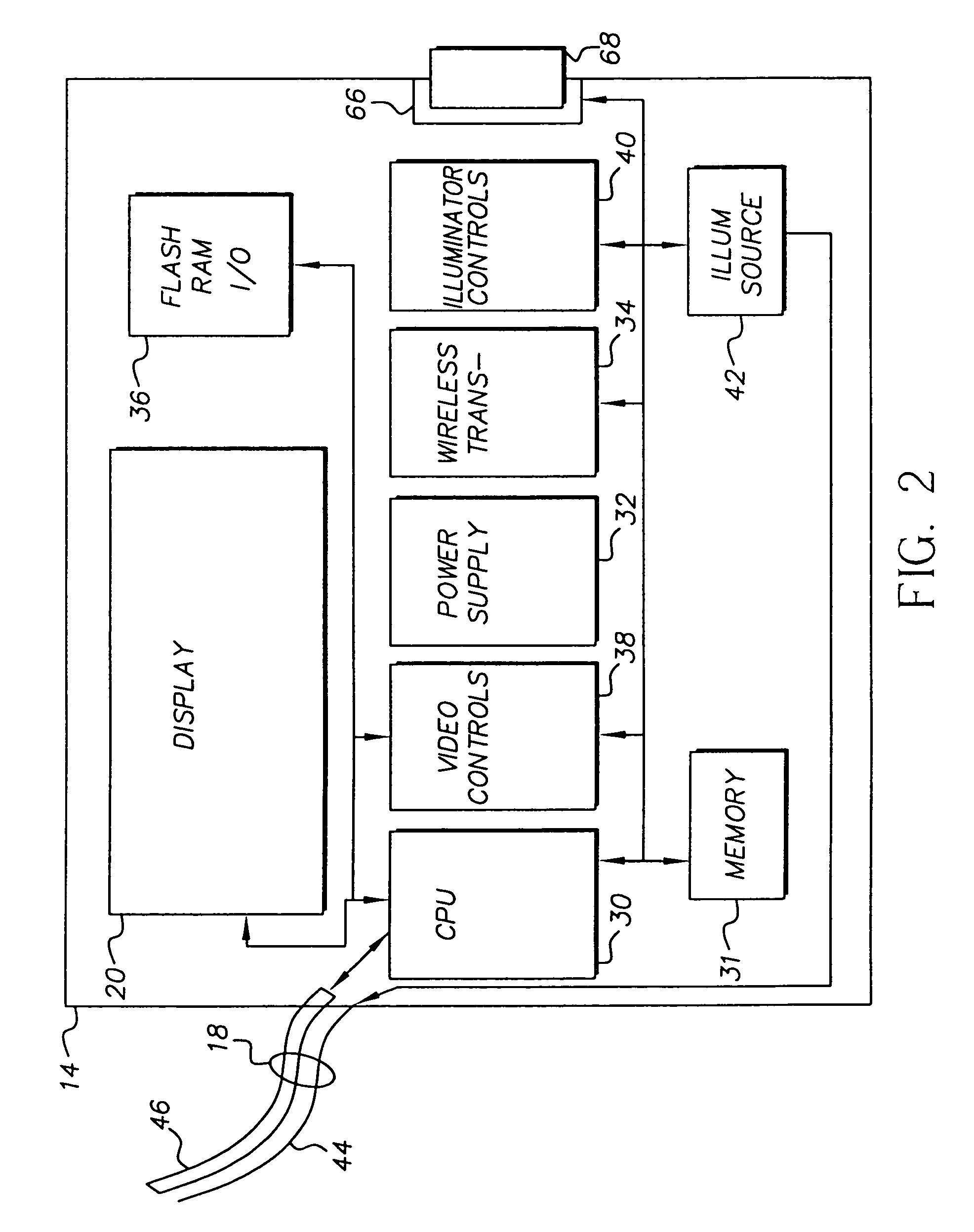
[0009]The advantage of the present invention lies in the integration of the display into a dental chair. This integration enables the practitioner to easily view and act upon the the results of image recording in close proximity to the capture location by interaction with the system, and conveniently display the captured image(s) either for the practitioner's or patient's benefit.

Problems solved by technology

For instance, in the Reveal® Imaging Platform sold by Welch Allyn® the monitor is mounted on top of the housing, which makes the whole assembly virtually unmovable.
Thus the practitioner is required to either purchase multiple camera systems or display capabilities for each operatory, as such display systems are rather large and bulky.
This process becomes cumbersome, costly, and inconvenient, as current camera systems are not designed for portability.

Method used


Image

  • Intra-oral camera system with chair-mounted display
  • Intra-oral camera system with chair-mounted display
  • Intra-oral camera system with chair-mounted display

Examples


second embodiment

[0035]In the intra-oral camera and display system shown in FIG. 5, the system includes a docking unit 100 with a recessed area 102 for mating with the integral base 14. The power supply 32 in the integral base 14 includes rechargeable batteries 104 connected to externally accessible charging electrodes 106. The docking unit 100 is provided with a battery charger 108 connected to externally accessible charging electrodes 110. When the integral base 14 is inserted into the recessed area 102 on the docking unit 100, the electrodes 106 and 110 are electrically connected and the batteries 104 are recharged.

third embodiment

[0036]In the intra-oral camera and display system shown in FIG. 6, the handpiece 16 of the system includes electronics and an interface for communicating with the integral base 14 across a wireless transmission linkage 116 or by means of a removable memory 118. More specifically, the handpiece 16 includes its own light source 120, processor 122, transceiver 124 and power supply 126. In addition, the power supply 126 may include rechargeable batteries 128, and the intra-oral camera and display system can further include a docking unit 130 with a battery charger 132. Both the handpiece 16 and the docking unit include mating electrodes 134 and 136 such that when the handpiece 16 is inserted into the docking unit 130, the electrodes 134 and 136 are electrically connected and the batteries 128 are recharged. In addition, as shown in FIG. 5, the integral base may have its own docking unit; moreover, the two docking units could be combined in one component.

[0037]Because of the likelihood o...


PUM


Abstract

A portable intra-oral capture and display system, designed for use by a dental practitioner in connection with a patient seated in a dental chair, includes: a handpiece elongated for insertion into an oral cavity of the patient, where the handpiece includes a light emitter on a distal end thereof for illuminating an object in the cavity and an image sensor for capturing an image of the object and generating an image signal therefrom; a monitor interconnected with the handpiece, where the monitor contains electronics for processing the image for display and a display element for displaying the image, where the interconnection between the monitor and the handpiece includes an electrical connection for communicating the image signal from the image sensor in the camera to the electronics in the monitor; and a receptacle on the dental chair for receiving the monitor, wherein the receptacle conforms to the monitor such that the monitor may be withdrawn from the receptacle in order to allow the display element to be seen by the dental practitioner or the patient.

Description

CROSS REFERENCE TO RELATED APPLICATIONS[0001]This patent application is a continuation-in-part of commonly-assigned U.S. patent application Ser. No. 10 / 238,174, which was filed on Sep. 10, 2002, which is a continuation-in-part of commonly-assigned U.S. patent application Ser. No. 09 / 796,239, which was filed on Feb. 28, 2001.FIELD OF THE INVENTION[0002]The present invention relates to intra-oral imaging systems for dental applications, and particularly to an intra-oral camera system that is used by a dental practitioner to display images of objects in the mouth.BACKGROUND OF THE INVENTION[0003]Electronic handheld cameras configured with intra-oral imaging optics are used for capturing images of the inside of a patient's mouth. The camera typically has an elongated body that contains an image sensor and optics. The optics and sensor are designed for capturing images of the inside of the mouth when the distal or viewing end of the camera is inserted into the patient's mouth. Wires carr...

Claims


Application Information

Patent Timeline
Patent Type & Authority Patents(United States)
IPC IPC(8): H04N7/18A61B1/00A61B1/04A61B1/24
CPCA61B1/00048A61B1/042A61B1/24A61B1/00016A61B2560/0456A61B1/00034
Inventor SQUILLA, JOHN R.BOLAND, JOHN T.SPOONHOWER, JOHN P.
Owner CARESTREAM HEALTH INC
Learn More