Signal transmission method in WDM transmission system, and WDM terminal, optical add-drop multiplexer node, and network element used in the same system

a transmission system and signal transmission technology, applied in the field of wavelength division multiplex (wdm) transmission technique, can solve the problems of low degree of freedom of the network, inability to flexibly perform active control according to the content of information about optical transmission signals, and inability to achieve maximum wdm transmission performance per channel, so as to prevent optical signal out-of-synchronism, reduce size and cost of oadm nodes, and improve the reliability of wdm transmission system

Inactive Publication Date: 2006-11-21
FUJITSU LTD
View PDF9 Cites 27 Cited by
  • Summary
  • Abstract
  • Description
  • Claims
  • Application Information

AI Technical Summary

Benefits of technology

[0033]The present invention has been made in view of the problems found in prior art. Accordingly, it is an object of the present invention to achieve a simplification in structure and a reduction in cost of an OADM and accordingly a WDM transmission system by constituting the OADM node without employing optical components such as optical switches, a rejection filer, etc. Another object of the invention is to enhance system performance per 1 channel of a WDM transmission system. Still another object of the invention is to flexibly increase or decrease the number of wavelengths during services.

Problems solved by technology

Conversely speaking, active control cannot be flexibly performed according to the content of information about an optical transmission signal, and it can also be said that the degree of freedom of the network is not high.
As a result, WDM transmission performance per one channel is not the maximum.
Therefore, in the case where a signal is added and dropped, the system becomes complicated, because it must be designed in consideration of the setting of a pass group.
Therefore, the number of wavelengths cannot be quickly and freely increased or decreased.
At the same time, the optical signal monitoring system based on the OSC becomes complicated.
Therefore, cost performance is extremely bad and the cost of the entire system becomes extremely high.
Therefore, an OSC of large capacity must be prepared and effective utilization of wavelength resources becomes difficult.
Therefore, once services are carried out, the wavelength adding-dropping structure cannot be changed unless the services are stopped.

Method used


Image

  • Signal transmission method in WDM transmission system, and WDM terminal, optical add-drop multiplexer node, and network element used in the same system
  • Signal transmission method in WDM transmission system, and WDM terminal, optical add-drop multiplexer node, and network element used in the same system
  • Signal transmission method in WDM transmission system, and WDM terminal, optical add-drop multiplexer node, and network element used in the same system

Examples


Embodiment Construction

[0093]Embodiments of the present invention will hereinafter be described with reference to the drawings.

[0094](A) Overview

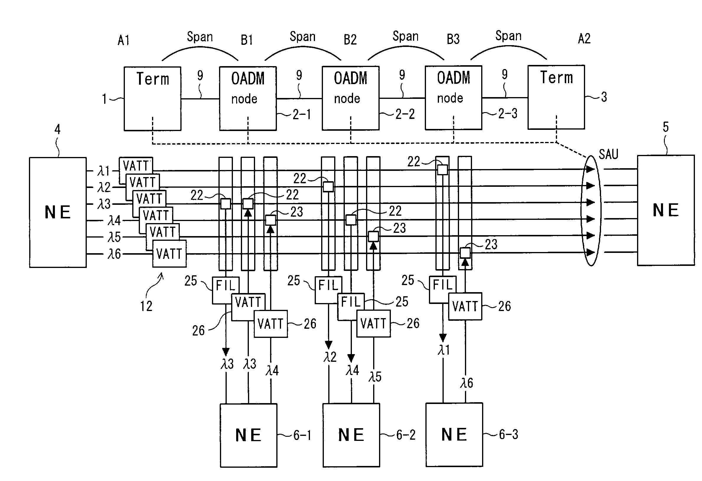
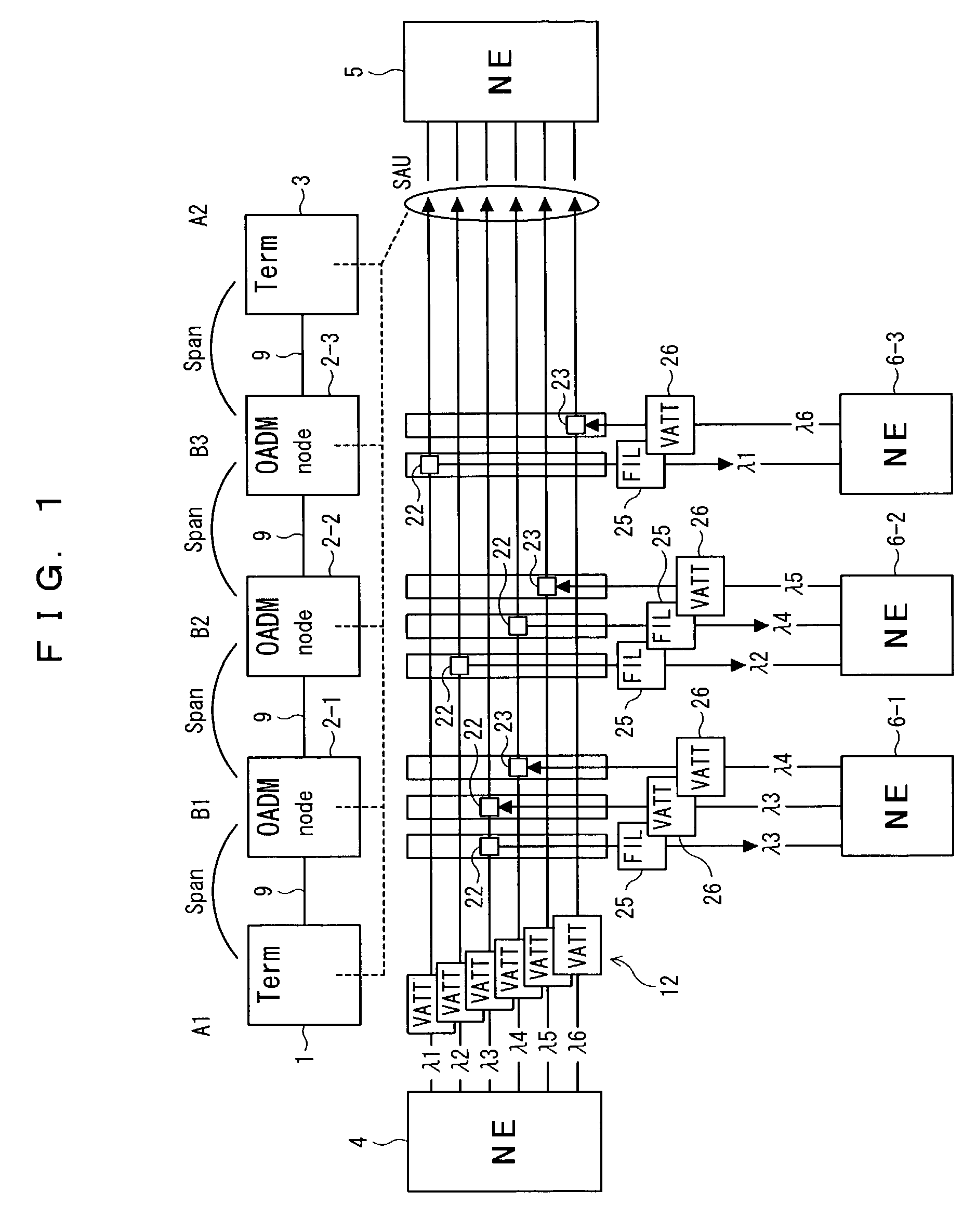
[0095]FIG. 1 shows a WDM transmission system constructed in accordance with a first embodiment of the present invention. As shown in the figure, the WDM transmission system includes a first WDM terminal 1 and a second WDM terminal 3. The first WDM terminal 1 is connected with a first NE 4. The second WDM terminal 3 is connected with a second NE 5 and provided in opposition to the first WDM terminal 1. The WDM transmission system further includes OADM nodes 2-1, 2-2, and 2-3, and NEs 6-1, 6-2, and 6-3 respectively connected to the OADM nodes 2-1, 2-2, and 2-3. Each of the OADM nodes 2-1, 2-2, and 2-3 performs a wavelength adding-dropping operation on a WDM signal which is transmitted between the first terminal 1 and the second terminal 3. The first terminal 1, the OADM nodes 2-1, 2-2, and 2-3, and the second terminal 3 are connected through an optical transmission...


PUM


Abstract

Disclosed herein is a signal transmission method in a wavelength-division-multiplex (WDM) transmission system. The WDM transmission system comprises a first WDM terminal for transmitting a WDM signal, a second WDM terminal for receiving the WDM signal, and an optical add-drop multiplexer (OADM) node for transmitting to a network element an optical signal of a specific wavelength of the WDM signal which is transmitted between the first and second WDM terminals. The WDM signal is transmitted from the first WDM terminal to the second WDM terminal regardless of whether an optical signal is added or dropped at the OADM node. The network element employs an optical signal of an idle wavelength of the WDM signal that has no transmission data, to transmit another transmission data that is transmitted by the network element.

Description

BACKGROUND OF THE INVENTION[0001](1) Field of the Invention[0002]The present invention generally relates to a wavelength-division-multiplex (WDM) transmission technique, and more particularly to a technique suitable for use in a WDM transmission system employing optical add-drop multiplexers for optical signals.[0003](2) Description of the Related Art[0004]It is desirable in the backbone of a network to change communication capacity according to a span between nodes constituting the network. This is because the span between nodes is about 80 km and has a different demand for communication. It is also desirable to allocate multiple wavelengths to a span that has a great demand for communication, because a demand for communication varies with a time zone of a day.[0005]Hence, an optical add-drop multiplexer (hereinafter referred to as an OADM node), capable of increasing or decreasing the number of wavelengths by dropping and adding optical signals, is employed in a WDM transmission s...

Claims


Application Information

Patent Timeline
Patent Type & Authority Patents(United States)
IPC IPC(8): H04J14/02H04B10/07H04B10/25H04B10/27H04B10/278H04B10/296H04B10/297H04B10/524H04B10/564H04B10/572H04J14/00H04Q3/52
CPCH04J14/0204H04J14/0205H04J14/0206H04J14/021H04J14/0213H04J14/0227H04J14/0283H04J14/0246H04J14/025H04J14/0212H04J14/0221H04J14/028
Inventor KURUMIDA, JUNYAIZUMI, FUTOSHI
Owner FUJITSU LTD
Why Eureka
Try Eureka