Encoding device and decoding device

a technology of encoding device and decoding device, which is applied in the field of encoding, can solve the problems of narrow bandwidth of sound and music reproduction, inability to maintain sound quality, etc., and achieve the effect of increasing the tonality of the higher frequency spectrum

Active Publication Date: 2006-11-21
DOLBY INT AB
View PDF9 Cites 51 Cited by
  • Summary
  • Abstract
  • Description
  • Claims
  • Application Information

AI Technical Summary

Benefits of technology

[0011]According to the decoding device of the present invention, since the gain adjustment is performed on the copied lower frequency components by adding noise spectrum to the higher frequency spectrum, there is an effect that the frequency band can be widened without extremely increasing the tonality of the higher frequency spectrum.

Problems solved by technology

However, if the encoding is conducted for reducing the data amount according to this method, the bandwidth for reproduction of sound and music becomes narrow.
As a result, it is impossible to maintain the sound quality.

Method used


Image

  • Encoding device and decoding device
  • Encoding device and decoding device
  • Encoding device and decoding device

Examples


first embodiment

(THE FIRST EMBODIMENT)

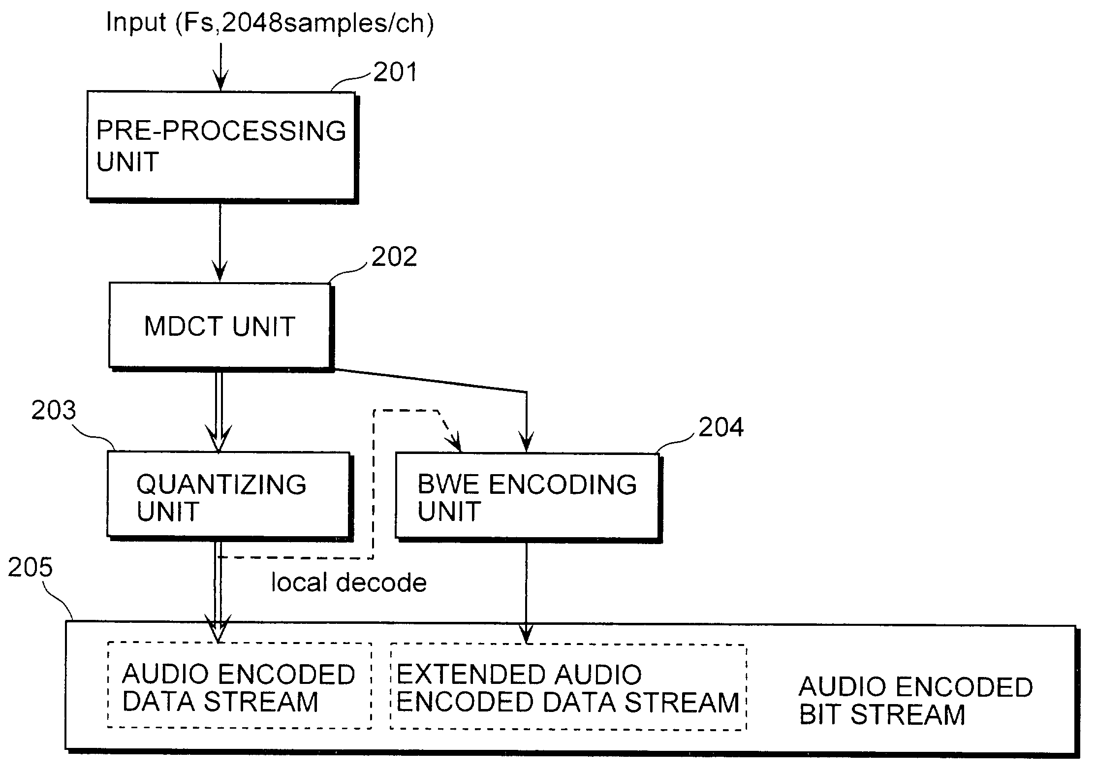
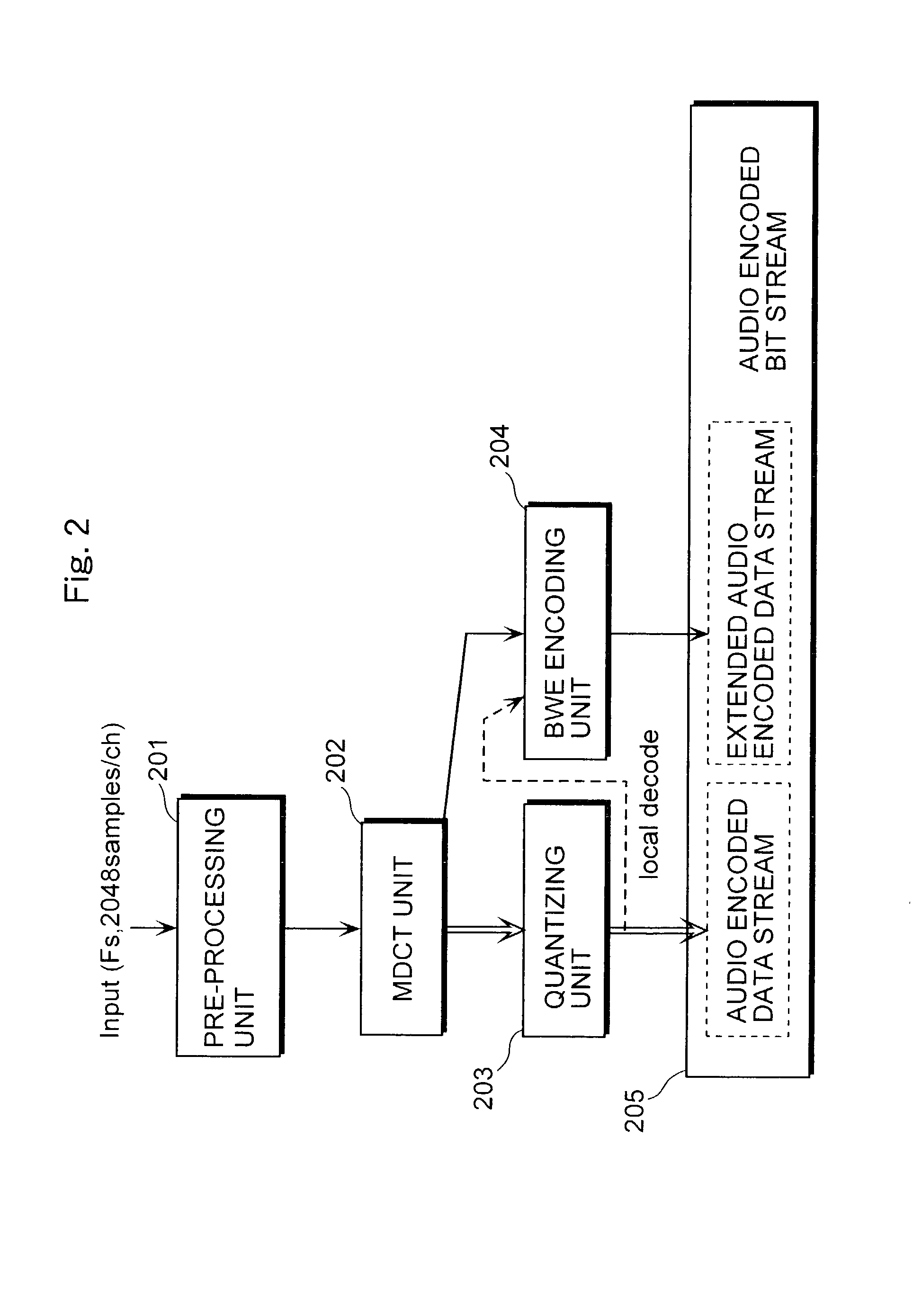
[0042]First, the encoding device will be explained. FIG. 2 is a block diagram showing a structure of the encoding device 200 according to the first embodiment of the present embodiment. The encoding device 200 is a device that divides the lower band spectrum into subbands in a fixed frequency bandwidth and outputs an audio encoded bit stream with data for specifying the subband to be copied to the higher frequency band included therein. The encoding device 200 includes a pre-processing unit 201, an MDCT unit 202, a quantizing unit 203, a BWE encoding unit 204 and an encoded data stream generating unit 205. The pre-processing unit 201, in consideration of change of sound quality due to quantization distortion with encoding and / or decoding, determines whether the input audio signal should be quantized in every frame smaller than 2,048 samples (SHORT window) giving a higher priority to time resolution or it should be quantized in every 2,048 samples (LONG window) ...

second embodiment

(THE SECOND EMBODIMENT)

[0088]The second embodiment of the present invention is different from the first embodiment in the following. That is, the BWE encoding unit 204 in the first embodiment divides a series of the lower band MDCT coefficients from the “startline” to the “endline” into 4 subbands A˜D, while the BWE encoding unit in the second embodiment divides the same bandwidth from the “startline” to the “endline” into 7 subbands A˜G with some parts thereof being overlapped. The encoding device and the decoding device in the second embodiment have a basically same structure as the encoding device 200 and the decoding device 600 in the first embodiment, and what is different from the first embodiment is only the processing performed by the BWE encoding unit 701 in the encoding device and the BWE decoding unit 702 in the decoding device. Therefore, in the second embodiment, only the BWE encoding unit 701 and the BWE decoding unit 702 will be explained with modified referential num...

third embodiment

(THE THIRD EMBODIMENT)

[0093]The third embodiment is different from the second embodiment in the following. That is, the BWE encoding unit 701 in the second embodiment divides a series of the lower band MDCT coefficients from the “startline” to the “endline” into 7 subbands A˜G with some parts thereof being overlapped, while the BWE encoding unit in the third embodiment divides the same bandwidth from the “startline” to the “endline” into 7 subbands A˜G and defines the MDCT coefficients in the lower subbands in the inverted order and the MDCT coefficients in the lower subbands whose positive and negative signs are inverted.

[0094]The components of the third embodiment different from the encoding device 200 and the decoding device 600 in the first and second embodiments are only the BWE encoding unit 801 in the encoding device and the BWE decoding unit 802 in the decoding device. The BWE encoding unit in the third embodiment will be explained below with reference to FIG. 8.

[0095]FIGS. ...


PUM


Abstract

An encoding device (200) includes an MDCT unit (202) that transforms an input signal in a time domain into a frequency spectrum including a lower frequency spectrum, a BWE encoding unit (204) that generates extension data which specifies a higher frequency spectrum at a higher frequency than the lower frequency spectrum, and an encoded data stream generating unit (205) that encodes to output the lower frequency spectrum obtained by the MDCT unit (202) and the extension data obtained by the BWE encoding unit (204). The BWE encoding unit (204) generates as the extension data (i) a first parameter which specifies a lower subband which is to be copied as the higher frequency spectrum from among a plurality of the lower subbands which form the lower frequency spectrum obtained by the MDCT unit (202) and (ii) a second parameter which specifies a gain of the lower subband after being copied.

Description

TECHNICAL FIELD[0001]The present invention relates to an encoding device that compresses data by encoding a signal obtained by transforming an audio signal, such as a sound or a music signal, in the time domain into that in the frequency domain, with a smaller amount of encoded bit stream using a method such as an orthogonal transform, and a decoding device that decompresses data upon receipt of the encoded data stream.BACKGROUND ART[0002]A great many methods of encoding and decoding an audio signal have been developed up to now. Particularly, in these days, IS13818-7 which is internationally standardized in ISO / IEC is publicly known and highly appreciated as an encoding method for reproduction of high quality sound with high efficiency. This encoding method is called AAC. In recent years, the AAC is adopted to the standard called MPEG4, and a system called MPEG4-AAC that has some extended functions added to the IS13818-7 is developed. An example of the encoding procedure is describ...

Claims


Application Information

Patent Timeline
Patent Type & Authority Patents(United States)
IPC IPC(8): G10L21/04G10L19/02
CPCG10L19/0208G10L21/038G10L19/0212G10L19/02
Inventor TSUSHIMA, MINEONORIMATSU, TAKESHINISHIO, KOSUKETANAKA, NAOYA
Owner DOLBY INT AB
Why Eureka
Try Eureka