Apparatus and method for lubricant condition control and monitoring

a technology of condition control and apparatus, applied in mechanical apparatus, pressure lubrication, machines/engines, etc., can solve the problems of premature wear and component or system failure, premature wear or even failure of machine elements, and achieve the effect of reducing or reducing the frequency of waveform

Inactive Publication Date: 2006-11-28
TRICO CORP
View PDF43 Cites 40 Cited by
  • Summary
  • Abstract
  • Description
  • Claims
  • Application Information

AI Technical Summary

Benefits of technology

[0011]Before proper lubrication of the rotating element can be achieved, there are a number of variables, which must be considered. These include the difference in lubrication level between the “on” and “off” operating modes (cycling modes) of the machine element being lubricated, the viscosity of the lubricant, the type of lubricant used and its condition, and the pressure within the lubrication system. It is a goal of the present invention to provide a volumetric lubricant dispenser, which can control all of the above noted variables and insure an acceptable operating condition. The device of the present invention is envisioned to be either automatic or manual in its mode of operation.

Problems solved by technology

Improper lubrication is likely to lead to premature component wear and component or system failure.
Although this type of lubricator provides reasonable performance in many steady-state operations, multiple variables can create unacceptable operating conditions and lead to premature wear, or even failure, of machine elements.

Method used


Image

  • Apparatus and method for lubricant condition control and monitoring
  • Apparatus and method for lubricant condition control and monitoring
  • Apparatus and method for lubricant condition control and monitoring

Examples


Embodiment Construction

[0031]Although the disclosure hereof is detailed and exact to enable those skilled in the art to practice the invention, the physical embodiments herein disclosed merely exemplify the invention which may be embodied in other specific structure. While the preferred embodiment has been described, the details may be changed without departing from the invention, which is defined by the claims.

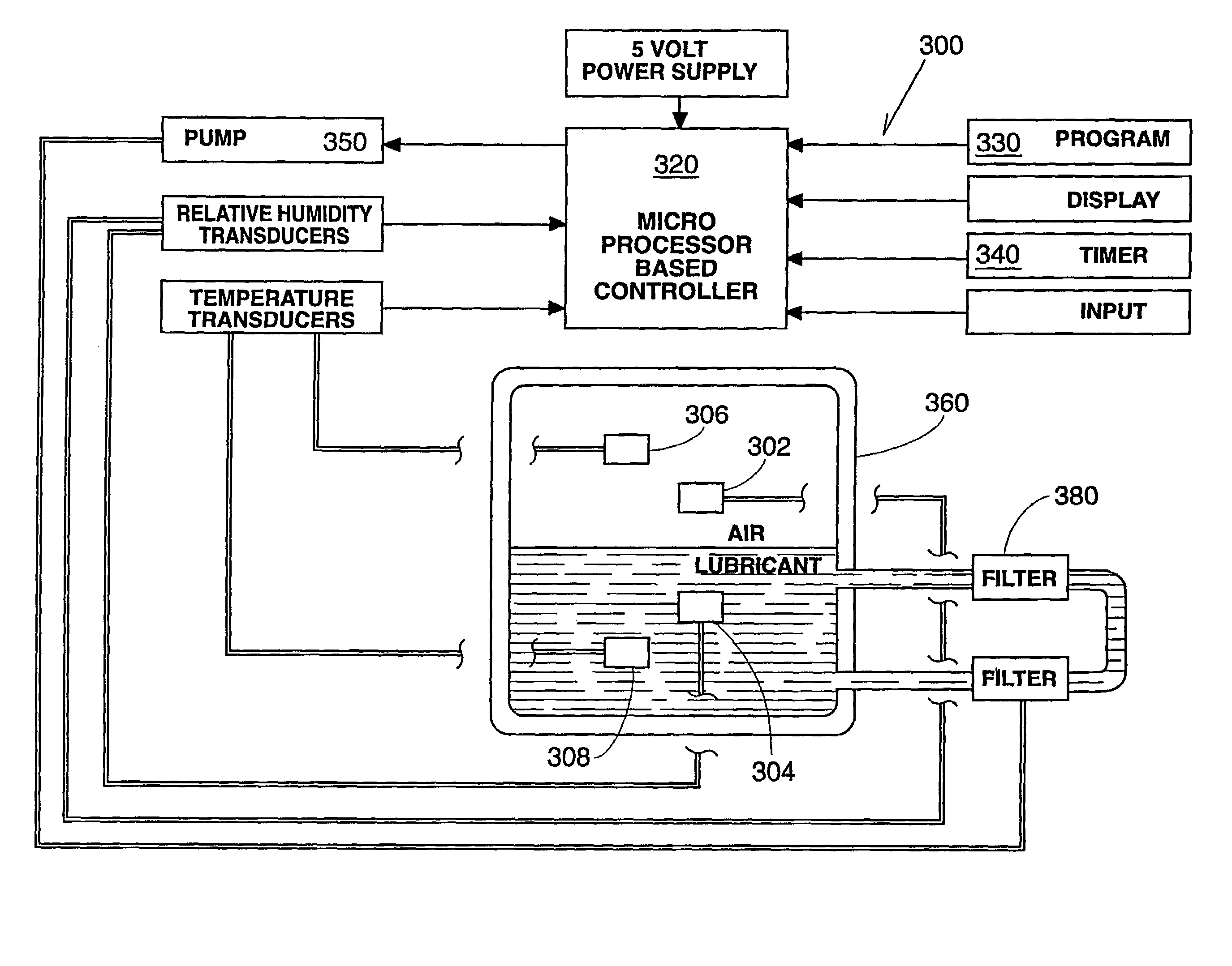
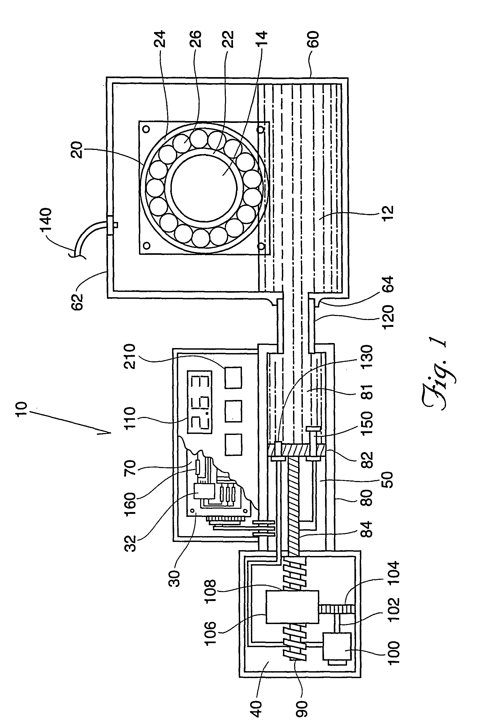
[0032]The present invention in one form comprises a volumetric lubricant dispensing apparatus. The invention is best shown in FIG. 1 at reference number 10. The components of my invention can be seen to include a control unit 30, a drive unit 40, a dispensing mechanism 50, a reservoir 60, a printed circuit board 70, a cylinder 80, a drive screw 90, a drive motor 100, a liquid crystal display 110 and an adapter fitting 120. In addition, there are multiple sensors that complete the system. These sensors include a temperature sensor 130, a vibration sensor 140, a pressure sensor 150 and a power primar...


PUM


Abstract

A plurality of sensors are utilized to record operating conditions of the machine, element, environment, and lubricant. The apparatus is controlled either manually or with the aid of a controller unit such as a microprocessor. A stand-alone humidity sensor mechanism is disclosed, in which signal process circuitry is electrically coupled to a humidity sensor, designed to be attached to the mechanism to be monitored so that it is juxtaposed in the atmosphere above the lubricant material that is being monitored.

Description

RELATED APPLICATIONS[0001]This application is a divisional of patent application Ser. No. 09 / 457,026 filed 8 Dec. 1999 now U.S. Pat. No. 7,017,712, which is a continuation-in-part of application Ser. No. 09 / 207,373 filed 8 Dec. 1998 now abandoned, which is a continuation-in-part of application Ser. No. 08 / 820,124 filed 19 Mar. 1997 (now U.S. Pat. No. 5,878,842); which claims the benefit of provisional application Ser. No. 60 / 085,643 filed 15 May 1998.BACKGROUND OF THE INVENTION[0002]Lubrication is an important aspect of maintaining machinery in proper operating condition. Machine elements such as bearings, journals, shafts, and joints require proper lubrication between their moving surfaces to decrease friction, prevent contamination, reduce wear and dissipate heat. Improper lubrication is likely to lead to premature component wear and component or system failure.[0003]When determining the optimal lubrication between moving machine elements, many factors should be considered. These ...

Claims


Application Information

Patent Timeline
Patent Type & Authority Patents(United States)
IPC IPC(8): F01M11/08F16N27/00F16N29/02F16N39/00
CPCF16N29/02F16N39/005F16N27/00F16N2230/02F16N2250/04F16N2250/08F16N2250/38
Inventor RAKE, BRADCRAVILLION, KEITHMOERTL, MARK
Owner TRICO CORP
Why Eureka
Try Eureka