Linear-feed irrigation apparatus and related method

a technology of linear movement and irrigation apparatus, which is applied in the field of linear movement irrigation apparatus, can solve the problems of clogging the sprinkler nozzle, affecting the flow rate of water, so as to reduce the load placed on the hydrant, reduce the load, and effectively capture the hydrant

Active Publication Date: 2006-11-28
PROJECT 088
View PDF34 Cites 14 Cited by
  • Summary
  • Abstract
  • Description
  • Claims
  • Application Information

AI Technical Summary

Benefits of technology

[0004]This invention relates to a unique “floating” docking station assembly that can be added to essentially any new or existing linear-move machine. The docking station assembly is supported and controlled so as to reliably and effectively capture each hydrant, open the hydrant water-supply valve to permit water to be supplied to the sprinklers on the truss assembly, close the valve, and then disengage from the hydrant for movement with the machine to the next hydrant. The “floating” docking station as described herein also minimizes the load placed on the hydrant, thus permitting a simpler main line construction.
[0014]It is another feature of the invention to facilitate different operating modes for the linear-move machine. For example, the machine may be used in a simple start / stop irrigation mode where the docking station is fixed to the side beam at the desired location, and the machine moves from hydrant to hydrant, stopping at each for a pre-programmed period of time for sprinkling. The water supply is cut off by a main control valve while the machine moves to the next hydrant.
[0015]It is also possible to manually adjust the position of the docking station along the side beam to vary the sprinkling pattern, for example, on the return path of the linear-move machine, to thereby provide more uniform application of water in the irrigated field. Alternatively, well-known drive and control devices may be utilized to automatically move the docking station along the side beam from one position to another.
[0017]In a full automatic mode, additional hardware changes are required. In the exemplary embodiment, parallel inner and outer fixed beams are attached to the end tower of the linear-move machine, and a docking station is mounted for reciprocatory movement on each. Flexible hoses connect each docking station to the distribution pipe on the truss assembly of the linear-move machine. At the same time, the water supply pipe is modified to the extent that alternate hydrants are offset in opposite lateral directions from the supply pipe to permit engagement with the respective inner and outer docking stations. The docking stations are movable along the respective inner and outer fixed beams by any suitable drive mechanism. In an exemplary mode of operation, the outer docking station will be located at the forward end of the outer fixed beam and engage a first outer hydrant. As the linear-move machine moves forward, the outer docking station will remain engaged and the inner docking station will move along the inner fixed beam and into engagement with the first inner hydrant. The outer docking station will disengage the first outer hydrant and move forward on the fixed outer beam, as the linear-move machine continues to move forward. This “leap-frog” process is repeated as the linear-move machine continues to travel along its path. In this way, no periodic shutdowns of the machine are required.
[0018]In all cases, the various operations of the linear-move machine and docking station(s) are controlled by a Programmable Logic Controller (PLC) located on the drive tower of the linear-move machine, operatively connected to a series of solenoids carried by the docking station supporting frame that control the various mechanical movements of the components. The PLC may be electronically “inserted between” the linear-move machine's PLC and the linear-move machine itself to permit seamless integration of the operation of both the linear-move machine and one or more docking stations.

Problems solved by technology

While linear-move machines can irrigate more area than center-pivot machines by reason of the resulting rectangularly-shaped irrigation pattern, the linear-move machines have proven to be problematic in several respects.
The most significant problem relates to the manner in which water is supplied to the machine.
Ditch water is typically filled with dirt and / or debris that can clog the sprinkler nozzles.
In other cases, one or more hoses are dragged by the machine the length of the field, requiring one or more manual attachment / detachment procedures and attendant issues of hose management.
In still other cases, complex mechanisms have been proposed for automatic docking with hydrants spaced along the length of a water supply pipe.
One of the problems with this arrangement is that the hydrant risers have had to be held firmly in concrete or welded onto steel pipe.
Alignment mechanisms have been complex and costly to maintain.
As a result, reliable docking under various conditions has proven to be an elusive goal, and we are unaware of any automatic docking mechanisms that have achieved a significant degree of commercial success to date.

Method used


Image

  • Linear-feed irrigation apparatus and related method
  • Linear-feed irrigation apparatus and related method
  • Linear-feed irrigation apparatus and related method

Examples


Embodiment Construction

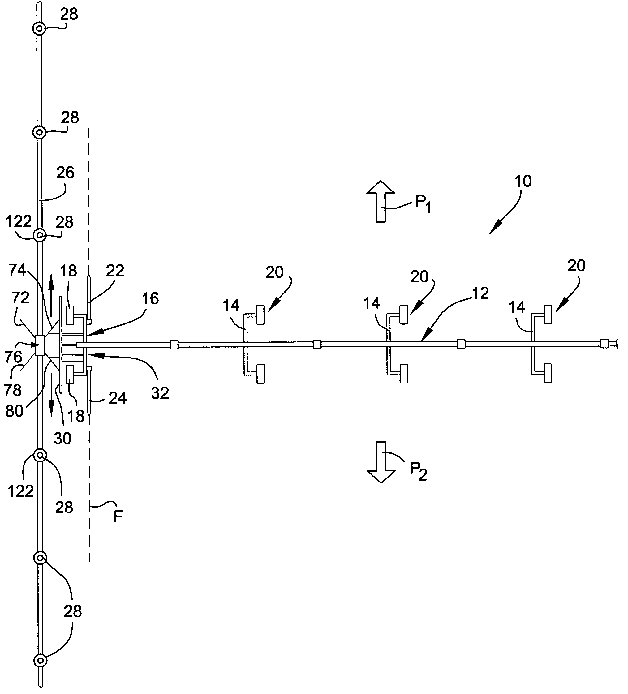
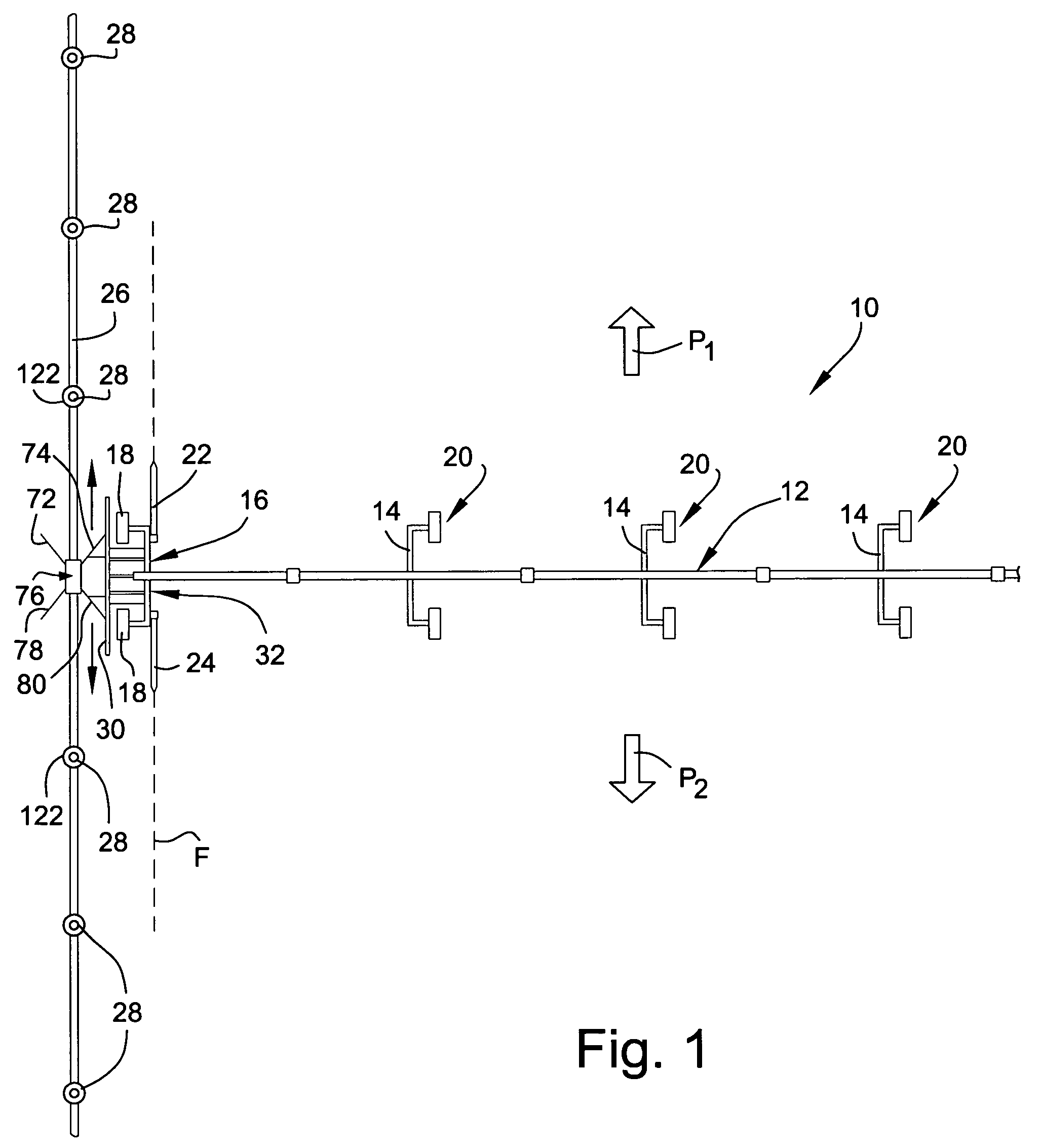
[0058]With reference initially to FIG. 1, a typical linear-move irrigation machine 10 includes a main truss assembly 12 supported by several wheeled towers 14 for movement in a forward direction along a linear path P1, or in a rearward direction along an opposite path P2. These paths extend perpendicularly to the truss assembly 12, and parallel to a water supply pipe 26. A drive tower 16 typically supports a generator (not shown) for supplying power to the drive wheels 18. In an end-feed arrangement, the drive tower is located at one end of the field, and the supply pipe 26 runs along that end of the field. In a center-feed machine, the drive tower is typically located in the center of the field and the supply pipe also runs through the center of the field. Separate electric motors (also not shown) are often attached to the remaining towers 14 for driving the respective wheel pairs 20 as needed to maintain alignment with the end tower 16 and associated drive wheels 18. Other drive a...


PUM


Abstract

A linear water feed apparatus for use in agricultural irrigation includes a linear-move machine with a mobile truss assembly supporting a plurality of individual sprinklers and adapted for movement in a specified direction across a field to be irrigated. The truss assembly is oriented transverse to the specified direction, and a supply pipe is arranged in the specified direction along or within the field to be irrigated. The supply pipe mounts a plurality of water supply hydrants at spaced locations along the pipe, each of the hydrants enclosing a water supply valve. A docking station is supported at one end of the truss assembly closest to the supply pipe, and is adapted to engage and open successive ones of the water supply valves in the plurality of hydrants. The docking station assembly includes a docking station that is suspended from a frame for floating movement about at least three mutually perpendicular axes.

Description

BACKGROUND OF THE INVENTION[0001]This invention relates to apparatus used for agricultural irrigation, and more specifically, to a linear water feed mechanism that automatically and successively engages and disengages spaced hydrants mounted on a water supply pipe extending alongside or through a field to be irrigated.[0002]Mobile irrigation systems having elevated boom or truss assemblies carrying multiple sprinklers are typically of the center pivot-type or the linear- (or lateral-) move-type. In a center-pivot machine, the elevated truss assembly pivots about an upright standpipe that supplies water to the sprinklers attached to the truss assembly. In a linear-move machine, the elevated truss assembly is carried on mobile, wheeled towers that move the machine linearly along a path that is perpendicular to the elevated boom or truss. Typically, the linear-move machine travels from one end of a field to the other and back again, and sprinkling typically occurs in both directions.[0...

Claims


Application Information

Patent Timeline
Patent Type & Authority Patents(United States)
IPC IPC(8): B05B3/00B05B1/20B05B3/02B05B3/18B05B9/00
CPCA01G25/097
Inventor SINDEN, JOSEPH D.NESS, REX D.LEINWEBER, CHAD D.BERRIER, RICHARD J.NELSON, CRAIGRUPAR, ROBERT
Owner PROJECT 088
Why Eureka
Try Eureka