Method and apparatus for detecting moisture in building materials

a technology for building materials and moisture, applied in the field of sensor systems, can solve the problems of occupants and structures being a danger to the occupants and the structure, difficulty in maintaining and protecting a building or complex, and extending the range of the system, so as to reduce the cost and prolong the system. the effect of the rang

Active Publication Date: 2006-11-28
GOOGLE LLC
View PDF90 Cites 150 Cited by
  • Summary
  • Abstract
  • Description
  • Claims
  • Application Information

AI Technical Summary

Benefits of technology

[0005]The present invention solves these and other problems by providing a relatively low cost, robust, wireless sensor system that provides an extended period of operability without maintenance. The system includes one or more intelligent sensor units and a base unit that can communicate with the sensor units. When one or more of the sensor units detects an anomalous condition (e.g., moisture, smoke, fire, water, etc.) the sensor unit communicates with the

Problems solved by technology

Maintaining and protecting a building or complex is difficult and costly.
Some conditions, such as fires, gas leaks, etc., are a danger to the occupants and the structure.
Other malfunctions, such as moisture in roofs, plumbing, walls, etc., are not necessarily dangerous for the occupants, but can, nevertheless, cause considerable damage.
Sensors can be used to detect such adverse ambient conditions,

Method used


Image

  • Method and apparatus for detecting moisture in building materials
  • Method and apparatus for detecting moisture in building materials
  • Method and apparatus for detecting moisture in building materials

Examples


Embodiment Construction

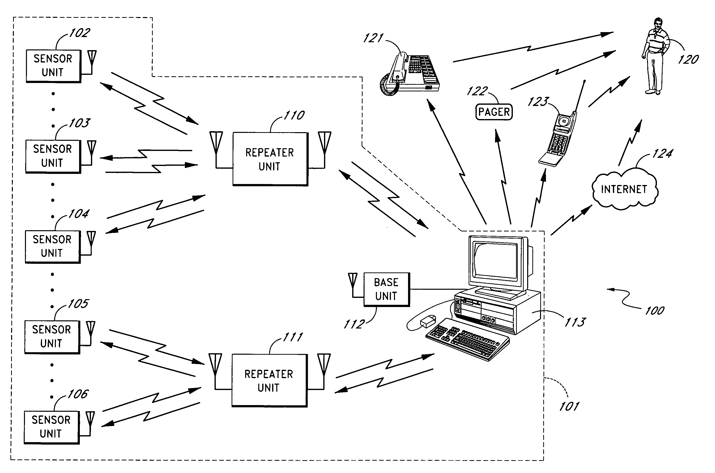
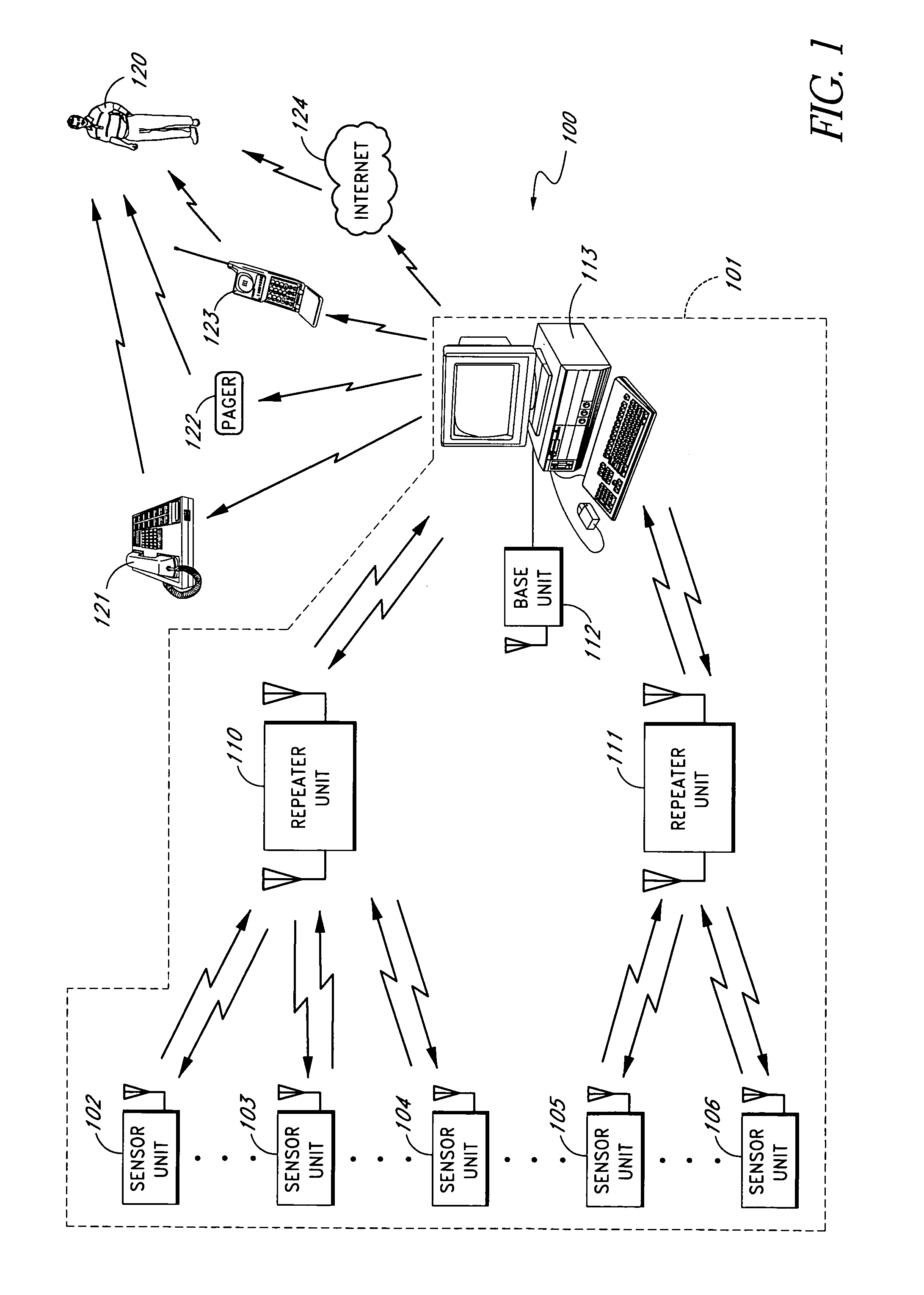
[0046]FIG. 1 shows a sensor system 100 that includes a plurality of sensor units 102–106 that communicate with a base unit 112 through a number of repeater units 110–111. The sensor units 102–106 are located throughout a building 101. Sensor units 102–104 communicate with the repeater 110. Sensor units 105–106 communicate with the repeater 111. The repeaters 110–111 communicate with the base unit 112. The base unit 112 communicates with a monitoring computer system 113 through a computer network connection such as, for example, Ethernet, wireless Ethernet, firewire port, Universal Serial Bus (USB) port, bluetooth, etc. The computer system 113 contacts a building manager, maintenance service, alarm service, or other responsible personnel 120 using one or more of several communication systems such as, for example, telephone 121, pager 122, cellular telephone 123 (e.g., direct contact, voicemail, text, etc.), and / or through the Internet and / or local area network 124 (e.g., through emai...


PUM


Abstract

A moisture sensor system is described. In one embodiment, the system provides an adjustable threshold level for the sensed moisture level. The adjustable threshold allows the moisture sensor to adjust to ambient conditions, aging of components, and other operational variations while still providing a relatively sensitive detection capability. In one embodiment, the adjustable threshold moisture sensor is used in an intelligent sensor system that includes one or more intelligent sensor units and a base unit that can communicate with the moisture sensor units. When one or more of the moisture sensor units detects a excess moisture the moisture sensor unit communicates with the base unit and provides data regarding the moisture condition. The base unit can contact a supervisor or other responsible person by a plurality of techniques, such as, telephone, pager, cellular telephone, Internet (and/or local area network), etc. In one embodiment, one or more wireless repeaters are used between the moisture sensor units and the base unit to extend the range of the system and to allow the base unit to communicate with a larger number of sensors.

Description

BACKGROUND OF THE INVENTION[0001]1. Field of the Invention[0002]The present invention relates to a sensor system for detecting and determining the severity of moisture in building materials, such as wood, drywall, plaster, etc.[0003]2. Description of the Related Art[0004]Maintaining and protecting a building or complex is difficult and costly. Some conditions, such as fires, gas leaks, etc., are a danger to the occupants and the structure. Other malfunctions, such as moisture in roofs, plumbing, walls, etc., are not necessarily dangerous for the occupants, but can, nevertheless, cause considerable damage. In many cases, an adverse ambient condition such as water leakage, fire, etc., is not detected in the early stages when the damage and / or danger is relatively small. Sensors can be used to detect such adverse ambient conditions, but sensors present their own set of problems. For example, adding sensors, such as, for example, smoke detectors, water sensors, and the like in an existi...

Claims


Application Information

Patent Timeline
IPC IPC(8): G08B21/00
CPCG01N27/048G08B19/00G08B21/20G08B25/009E04F19/04E04F2019/0422G01N27/04G01N33/38
Inventor KATES, LAWRENCE
Owner GOOGLE LLC
Why Eureka
Try Eureka