Turbidity sensor

a technology of turbidity sensor and liquid, which is applied in the field of liquid turbidity measurement system, can solve the problems of not meeting epa 180.1, water is aesthetically objectionable, and the trap does not serve as a fluid inlet, so as to improve the sensitivity of industrial optical sensor

Active Publication Date: 2006-11-28
ECOLAB USA INC
View PDF9 Cites 41 Cited by
  • Summary
  • Abstract
  • Description
  • Claims
  • Application Information

AI Technical Summary

Benefits of technology

[0009]It is an object of the present invention to improve sensitivity of an industrial optical sensor for measuring turbidity and to provide an optical design, which allows installing an incandescent lamp according to the EPA 180.1 or installing an infrared LED according to the ISO7027.
[0010]It is an object of the present invention to provide a turbidity sensor that can be used with use two replaceable light sources to meet both EPA 180.1 and ISO 7027 methods.
[0011]It is another object of the present invention to improve the measurement range of a turbidity sensor so to provide several optical channels with different sensitivities.
[0012]It is another object of the present invention to improve a sample chamber for the turbidity sensor to eliminate stray light and decrease particle and bubble accumulation during operation. It is further object of the present invention to improve a turbidity measuring system with a faster time response or to decrease the flow rate with an identical response time as the prior art.

Problems solved by technology

Excessive amounts of turbidity also make water aesthetically objectionable.
Also, its light traps do not serve as a fluid inlet.
Moreover, it does not comply with EPA 180.1 as it does not use any tungsten lamp as a light source.

Method used


Image

  • Turbidity sensor
  • Turbidity sensor
  • Turbidity sensor

Examples


Embodiment Construction

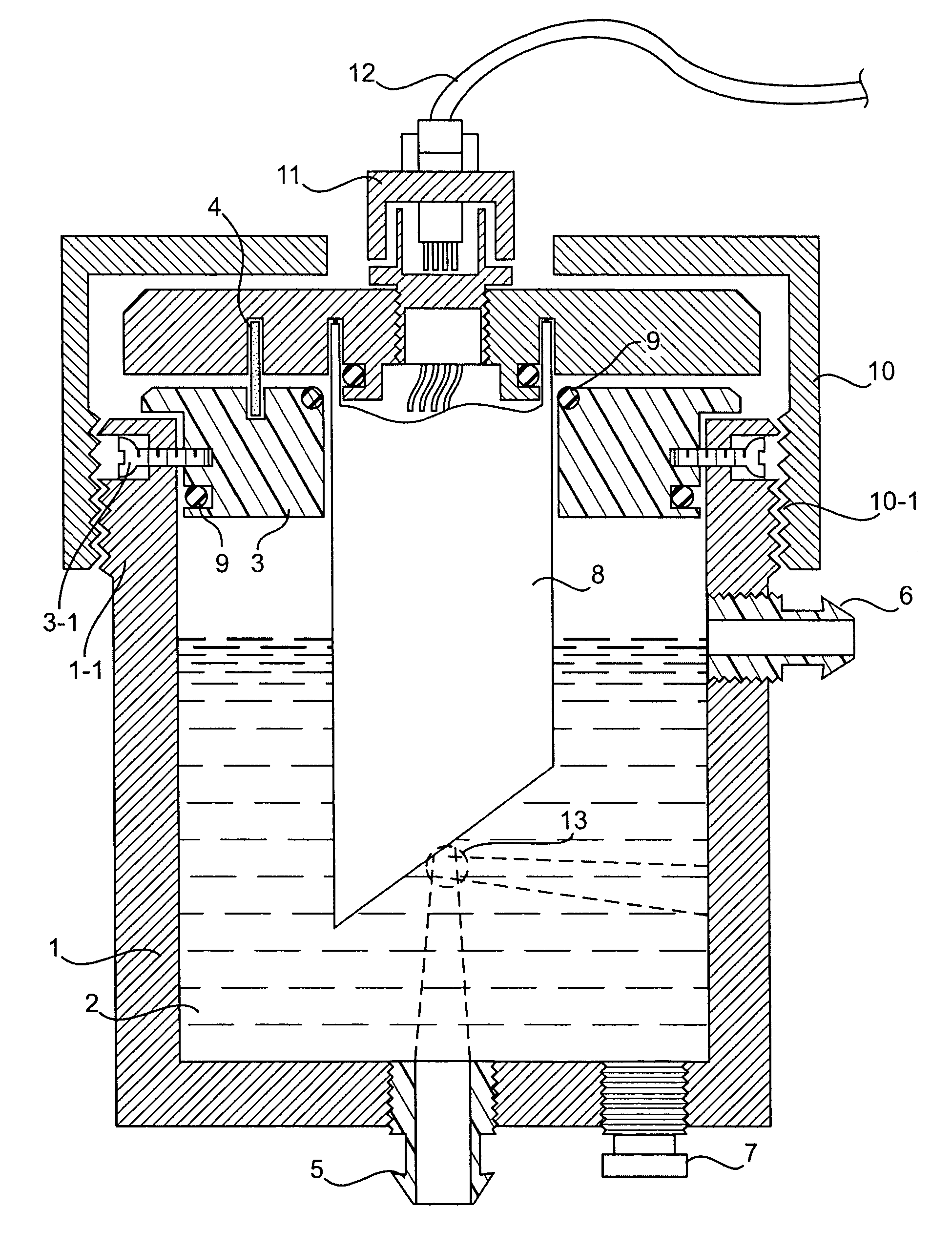
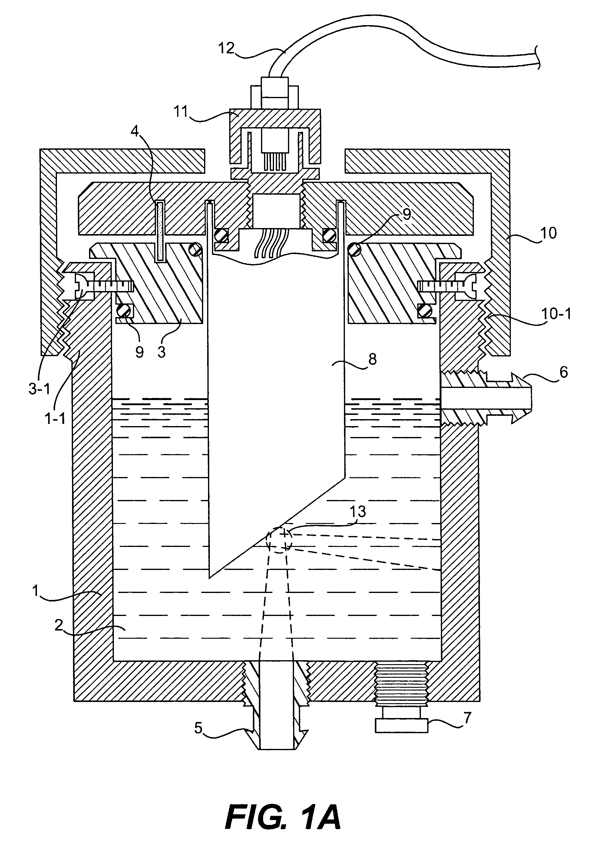
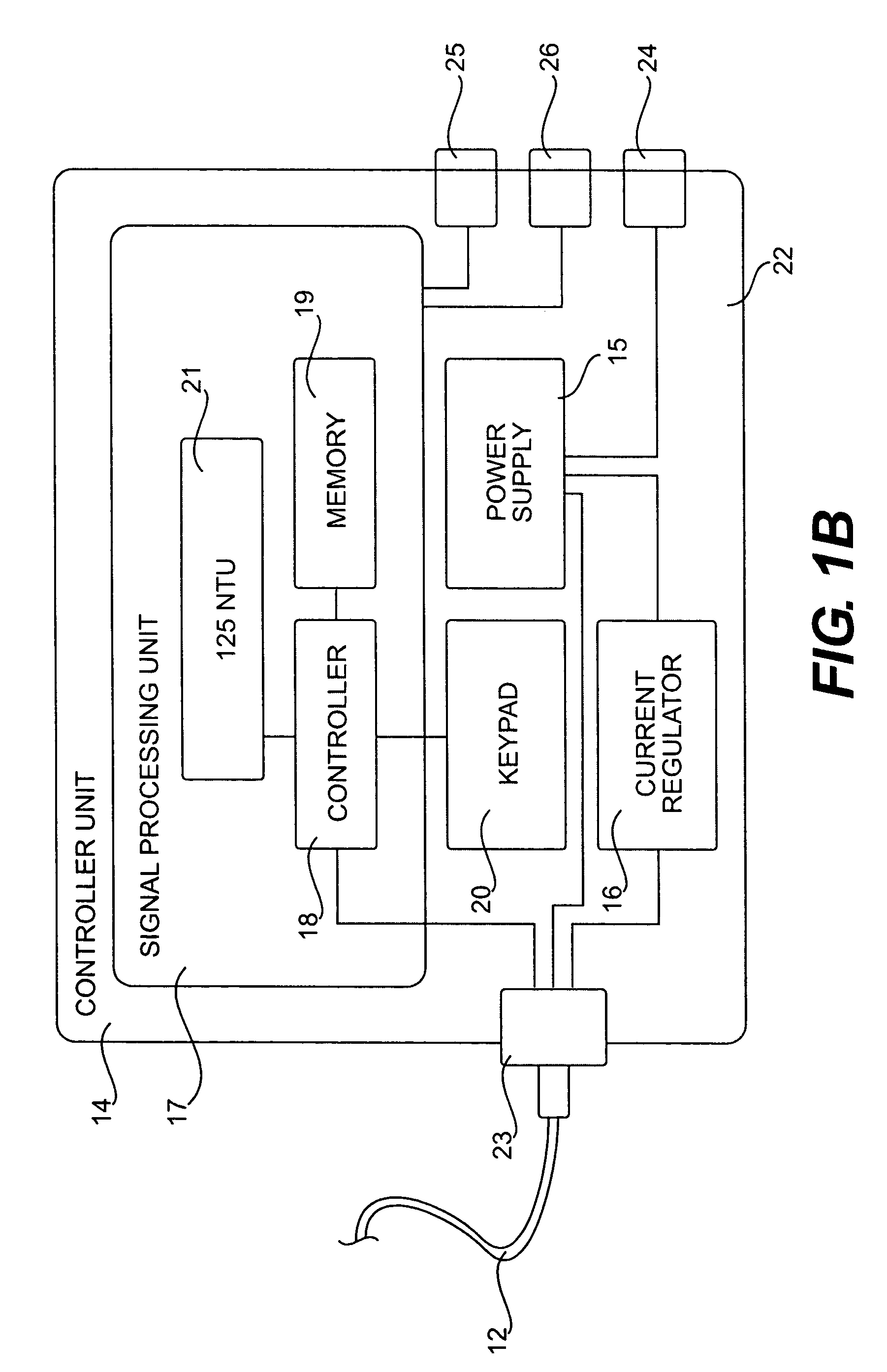
[0027]In FIG. 1A, a turbidity sensor for testing a fluid sample 2 according to the present invention includes a sample chamber 1, a sensor unit 8, and a controller unit 14. The sample chamber 1 has at the top portion a mounting ring 3 for inserting the sensor unit 8 and a positioning pin 4, at least one inlet 5, at least one outlet 6, a plug 7 for releasing the sample 2 when necessary (e.g., cleaning), a chamber cap 10 with threads 10-1 on the inner surface to be screwed with threads 1-1 on the outer surface of the chamber 1, a cable connector 11 connecting a cable 12 to the sensor unit 8. The mounting ring 3 can be secured to the chamber 1 via a pair of screws 3-1. Some O-rings 9 are provided between the chamber 1, the mounting ring 3 and the sensor unit 8 to secure and seal them against each other. The cable 12 transfers signals between the sensor unit 8 and a controller unit 14 shown in FIG. 1B. The sample chamber 1 and the chamber cap 10 are made of an opaque material, such as a...


PUM

PropertyMeasurementUnit
angleaaaaaaaaaa
scattering anglesaaaaaaaaaa
angleaaaaaaaaaa

Abstract

A turbidity measuring system is provided with a chamber and a sensor having a watertight housing, a light source, a first light focusing device for focusing a light emitted from the light source and passing therethough into a sample liquid, a second light focusing device for collecting at least one scattered light resulted form the focused light when passing the sample liquid, a photodiode for receiving the collected light thereby generating electronic signals, and an electronic board for processing the electronic signals. In particular, the watertight housing has a tilted bottom, the light detector includes at least two photodiodes for detecting separated turbidity measuring ranges, or an insert is placed at the bottom of the chamber having first and second insert channels each of whose axis pointing toward an axis of one of the cylindrically-shaped channels in the watertight housing in order to trap light.

Description

BACKGROUND OF THE INVENTION[0001]1. Field of the Invention[0002]The invention relates generally to a system for measuring turbidity of liquids, and more particularly to a system including a chamber for receiving a sample liquid, a cover for covering the chamber; and a sensor unit with its bottom immersed in the sample liquid.[0003]2. Description of Related Arts[0004]Turbidity sensors measure suspended matters in water that interfere with the passage of light through the water or in which visual depth is restricted. The turbidity may be caused by a wide variety of suspended materials, such as clay, silt, finely divided organic and inorganic matter, soluble colored organic compounds, plankton and other microscopic organisms and similar substances. Turbidity in water has public health implications due to the possibilities of pathogenic bacteria encased in the particles and thus escaping disinfection processes. Excessive amounts of turbidity also make water aesthetically objectionable. ...

Claims


Application Information

Patent Timeline
Patent Type & Authority Patents(United States)
IPC IPC(8): G01N21/00
CPCG01N21/53
Inventor TOKHTUEV, EUGENESKIRDA, ANATOLYOWEN, CHRISTOPHER J.CHRISTENSEN, WILLIAM
Owner ECOLAB USA INC
Why Eureka
Try Eureka