Fixing device and image forming apparatus

a fixing device and image forming technology, applied in the field of fixing devices and image forming apparatus, can solve the problems of sharp increase of load torque, breakage of driving portion or damage to the surface of the roller, etc., and achieve the effect of reducing sliding frictional resistance with the endless bel

Inactive Publication Date: 2006-11-28
RICOH PRINTING SYST
View PDF17 Cites 19 Cited by
  • Summary
  • Abstract
  • Description
  • Claims
  • Application Information

AI Technical Summary

Benefits of technology

[0012]According to the invention, by allowing the sliding layer of the fixing device to comprise two layers, a holding property of the lubricant comes to be excellent and sliding frictional resistance with the endless belt can be reduced.

Problems solved by technology

In a fixing device adopted an endless belt, when a frictional force between the belt and the sliding layer is high, the load torque becomes large to sometimes cause a breakage of a driving portion or a damage of the surface of the roller.
Further, when the oil holding ratio of the sliding layer is small, a problem is sometimes generated in that the lubricant is seeped out and enter between the roller and the belt to cause a slip of the belt, or the lubricant is depleted in the sliding portion in a long-hour driving to cause a sharp increase of the load torque.

Method used


Image

  • Fixing device and image forming apparatus
  • Fixing device and image forming apparatus
  • Fixing device and image forming apparatus

Examples


example 1

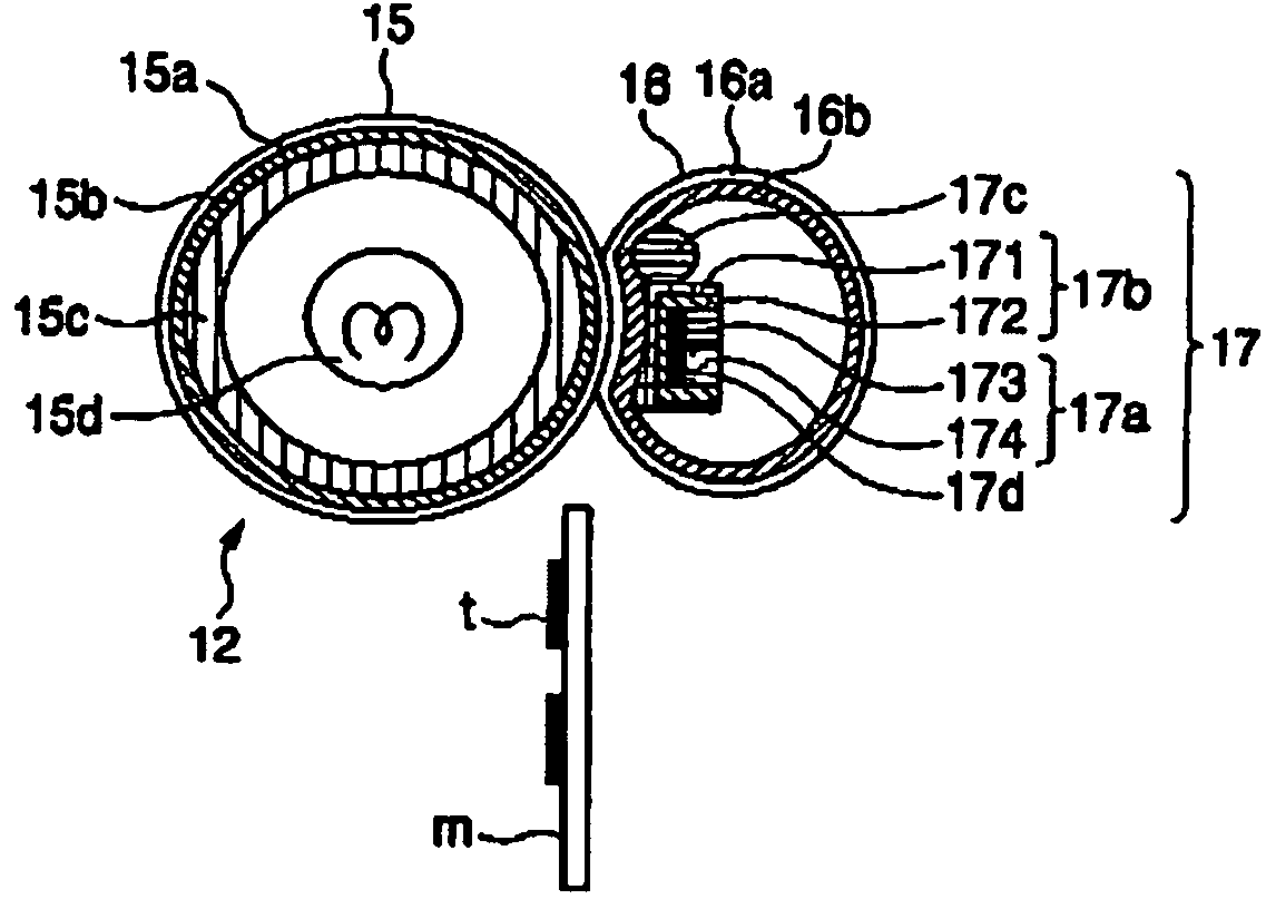
[0042]In regard to a roller 15, a PFA tube having a thickness of 30 μm was used as a toner parting layer 15a; a silicone rubber having a thickness of 0.6 mm and a hardness of 20° (Shore hardness A) was used as an elastic layer 15b; and a cylinder made of aluminum having a thickness of 1 mm and a diameter of 40 mm was used as a support 15c.

[0043]In regard to an endless belt 16, a PFA tube having a thickness of 30 μm was used as a surface layer 16a; and a polyimide belt having a thickness of 50 μm and a diameter of 30 mm was used as a substrate 16b.

[0044]In regard to a pressure-applying member 17, an aluminum pad 173 and a silicone rubber pad 174 having a hardness of 20° (Shore hardness A) and a thickness of 4 mm was used as a pressing member 17a; a fluorine felt (available from Toray Industries, Inc.) having a thickness of 0.8mm was used as a sliding layer 17b; and a roller made of stainless steel having a diameter of 8 mm was used as a releasing roller 17c.

[0045]In regard to a he...

example 2

[0051]Same procedures as in Example 1 were performed except that a layer 172 on the side of being not in contact with an endless belt 16 was changed into an aramid felt having a thickness of 0.4 mm and a layer 171 on the side of being in contact with the endless belt 16 was changed into a porous PTFE film (available as POREFLON from Sumitomo Electric Industries, Ltd.)

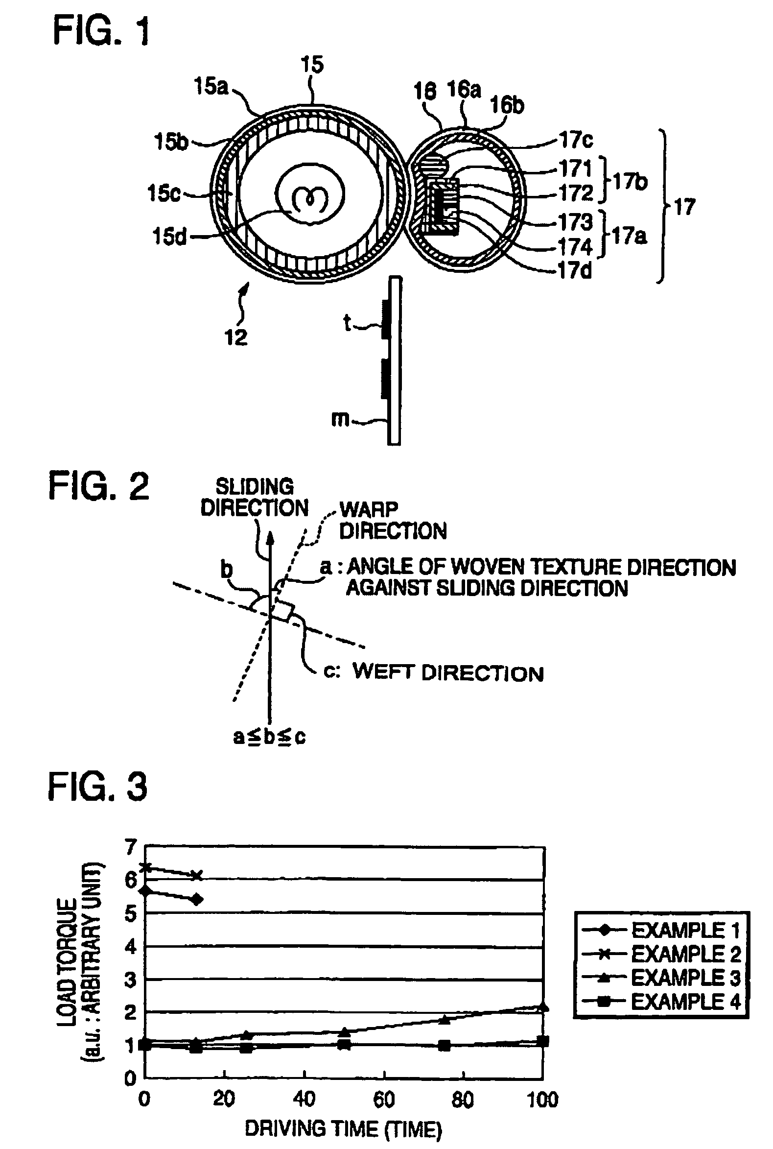
[0052]According to Example 2, an oil component holding ratio was large as 86% while an effective contact area ratio was extremely large as 99%. The load torque in the above case was 6.1 (a.u.) when a driving time duration was 12.5 hours.

example 3

[0053]Same procedures as in Example 1 were performed except that a layer 172 on the side of being not in contact with an endless belt 16 was changed into a PTFE woven fabric (available as No. 406W from Toray Industries, Inc.) having a thickness of 0.4 mm and a layer 171 on the side of being in contact with the endless belt 16 was changed into a PFA net (available from Toray Industries, Inc.) and, also, a woven texture direction was changed to 45° against a sliding direction.

[0054]According to Example 3, an oil component holding ratio was small as 25% while an effective contact area ratio was extremely small as 1%. The load torque in the above case was 1.1 (a.u.) when a driving time duration was 12.5 hours. Although this value was lower than those in Examples 1 and 2, it was increased to 2.2 when the driving time duration was 100 hours.


PUM


Abstract

A fixing device includes a roller; an endless belt which is in contact with the roller and rotates with a circulation of the roller in a follower manner; a heating source in at lease one of an inside of the roller and an inside of the endless belt; and a pressure-applying member which is inside the endless belt and presses the endless belt against the roller. A sliding layer is provided on a side on which the pressure-applying member is in contact with the endless belt, and the sliding layer comprises at least two layers and holds a lubricant.

Description

BACKGROUND OF THE INVENTION[0001]1. Field of the Invention[0002]The present invention relates to a belt fixing device which fixes an unfixed toner held on a recording medium such as paper or an OHP sheet based on print data and an image forming apparatus provided with the belt fixing device.[0003]2. Description of the Related Art[0004]In an image forming apparatus provided with a belt fixing device such as a laser beam printer, it is essential to stably drive a belt for a long period of time.[0005]As for a conventional technique, there is a case in which an article in which a porous resin film is laminated on a surface of a porous resin fiber woven fabric or a porous resin fiber woven fabric is used as a low friction sheet and silicon oil is used as a lubricant (see JP-A-2001-228731). However, since a void in a pressed portion of a porous resin is crushed and the lubricant is pushed out, a lean state of the lubricant is generated. Therefore, a load torque is increased in proportion ...

Claims


Application Information

Patent Timeline
Patent Type & Authority Patents(United States)
IPC IPC(8): G03G15/20G03G15/00
CPCG03G15/206G03G2215/2009G03G2215/2093G03G15/2064
Inventor KOYAMA, TUYOSHIOGISO, TOSHIOHIRAOKA, CHIKARAKIKUCHI, KAZUOTAKEGOSHI, TETSUJIHANASHIMA, TORUUKEI, SHOJI
Owner RICOH PRINTING SYST
Why Eureka
Try Eureka