Apparatus and method for digital image correction in a receiver

a receiver and digital image technology, applied in the field of radio frequency communication systems, can solve the problems of increasing difficulty and bulky implementation of narrow-bandwidth bandpass filters, interference with the information content of the desired rf signal, and difficulty in filter implementation

Active Publication Date: 2006-11-28
SILICON LAB INC
View PDF10 Cites 133 Cited by
  • Summary
  • Abstract
  • Description
  • Claims
  • Application Information

AI Technical Summary

Problems solved by technology

However, narrow-bandwidth bandpass filters become increasingly difficult and bulky to implement as their center frequencies increase.
However, if another RF signal is present at 990 MHz, this signal will also be translated to the 10 MHz IF, which may result in interference with the information content of the desired RF signal.
However, as noted above, such a filter may be difficult to implement, which is a primary motivation for implementing a heterodyne system.
However, imbalances in gain and phase relationships between the two paths may yield imperfect image frequency rejection, resulting in undesired interference that may require further filtering or correction.

Method used


Image

  • Apparatus and method for digital image correction in a receiver
  • Apparatus and method for digital image correction in a receiver
  • Apparatus and method for digital image correction in a receiver

Examples


Embodiment Construction

[0028]Overview of System and Image Phenomenon

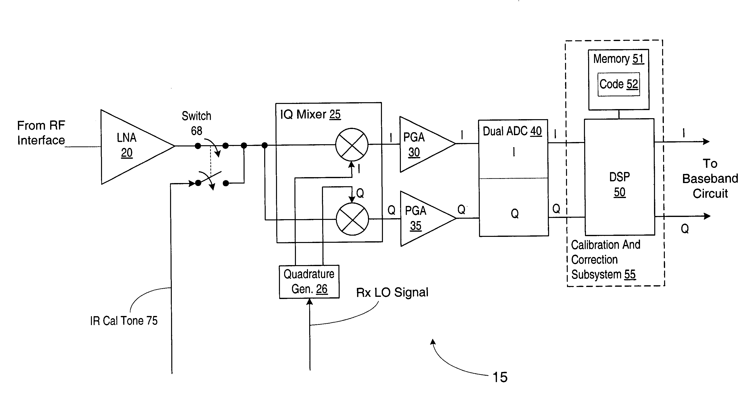
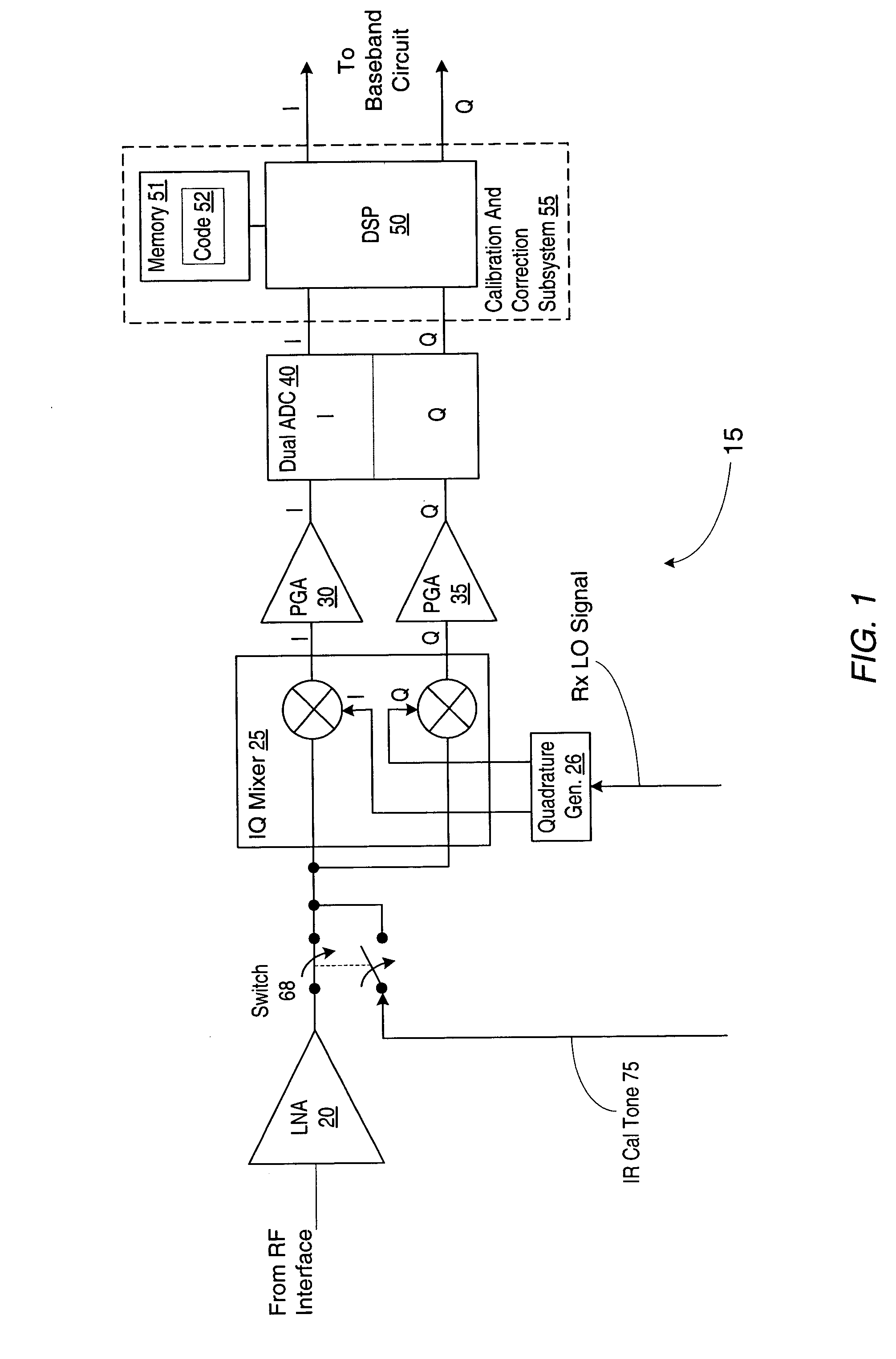
[0029]Turning now to FIG. 1, a block diagram of one embodiment of a receiver system 15 is shown. Receiver system 15 may be configured to operate within a wireless communication device, such as a cellular telephone handset or a wireless data modem, for example. Additionally, receiver system 15 may be configured to implement one or more specific communication protocols or standards, such as the Global System for Mobile Communications (GSM) standard, the Personal Communications Service (PCS) standard, the Digital Cellular System (DCS) standard, the General Packet Radio Service (GPRS) standard, and / or the Enhanced General Packet Radio Service standard (E-GPRS, which may also be referred to as the Enhanced Data for GSM Evolution (EDGE) standard), for example. In general, receiver subsystem 15 may be configured to receive an incoming radio frequency (RF) signal from an RF interface (not shown), which may include elements such as an antenna, fil...


PUM


Abstract

An apparatus and method for performing digital image correction in a receiver. In one embodiment, a receiver circuit may include an IQ signal source configured to provide a digital signal comprising in-phase (I) and quadrature (Q) components, such as an IQ mixer in combination with an analog to digital converter, for example. The receiver circuit may also include an image correction unit coupled to the IQ signal source and configured to combine the digital signal with a complex image correction factor. The image correction unit may be implemented using a digital signal processor under the control of associated program instructions, for example. In one specific implementation of the receiver circuit, the image correction unit may be configured to combine the digital signal with the complex image correction factor using a cross-accumulation operation.

Description

BACKGROUND OF THE INVENTION[0001]1. Field of the Invention[0002]This invention relates to radio frequency communication systems and, more particularly, to correction of received image frequency signals in receiver systems.[0003]2. Description of the Related Art[0004]In many modern communication systems, information is transmitted and received by modulating a radio frequency (RF) carrier signal with a data signal and then demodulating the RF signal to recover the data signal. Demodulating an RF carrier signal usually involves tuning a receiver to the carrier signal, which may be at a substantially higher frequency than the frequencies of the data it conveys. For example, a carrier signal frequency may be on the order of 1–2 GHz, whereas the bandwidth of the data channel conveyed by the carrier signal may be on the order of only 100–200 kHz.[0005]In one approach to demodulating an RF signal, a bandpass filter having a bandwidth approximately equal to the data channel bandwidth may be ...

Claims


Application Information

Patent Timeline
Patent Type & Authority Patents(United States)
IPC IPC(8): H04B17/02H04B17/40H03D3/00H04B1/28
CPCH03D3/009H04B1/0007H04B1/001H04B1/28
Inventor PAULUS, TOD
Owner SILICON LAB INC
Why Eureka
Try Eureka