
Method and apparatus for improving wireline depth measurements

a technology of depth measurement and wireline, applied in the direction of instruments, survey, borehole/well accessories, etc., can solve the problems of friction being the least predictable, tension also affected, and the determination of friction even more difficul

Inactive Publication Date: 2006-11-28
BAKER HUGHES HLDG LLC
View PDF6 Cites 26 Cited by
  • Summary
  • Abstract
  • Description
  • Claims
  • Application Information

AI Technical Summary

Benefits of technology

This approach provides accurate and real-time depth estimation with reduced errors, capable of handling varying borehole inclinations and severe washouts, while minimizing assumptions about noise and measurement characteristics.

Problems solved by technology

Tension is also affected by the weight of the instrument when it is inserted into the wellbore, which weight can vary depending on instrument density (related to the weight of the instrument and how much of the instrument volume is enclosed air space) and the density of a fluid (“drilling mud” or “completion fluid”) which may fill the wellbore, and can also be affected by friction caused by movement of the instrument against the wall of the wellbore.
Friction is the least predictable of the causes of tension on the cable as it is moved into and out of the wellbore because the wall surface of the wellbore has an indeterminate degree of roughness and the earth formations penetrated by the wellbore have indeterminate frictional coefficients.
The fluid which typically fills the wellbore can have indeterminate viscosity and lubricating properties at different depths within a particular wellbore, making determination of friction even more difficult.

Method used


Image

  • Method and apparatus for improving wireline depth measurements
  • Method and apparatus for improving wireline depth measurements
  • Method and apparatus for improving wireline depth measurements

Examples


Embodiment Construction

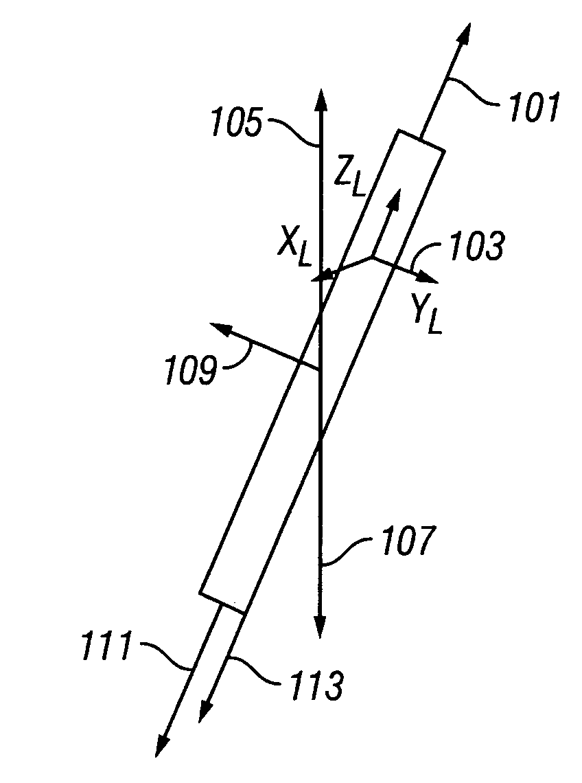
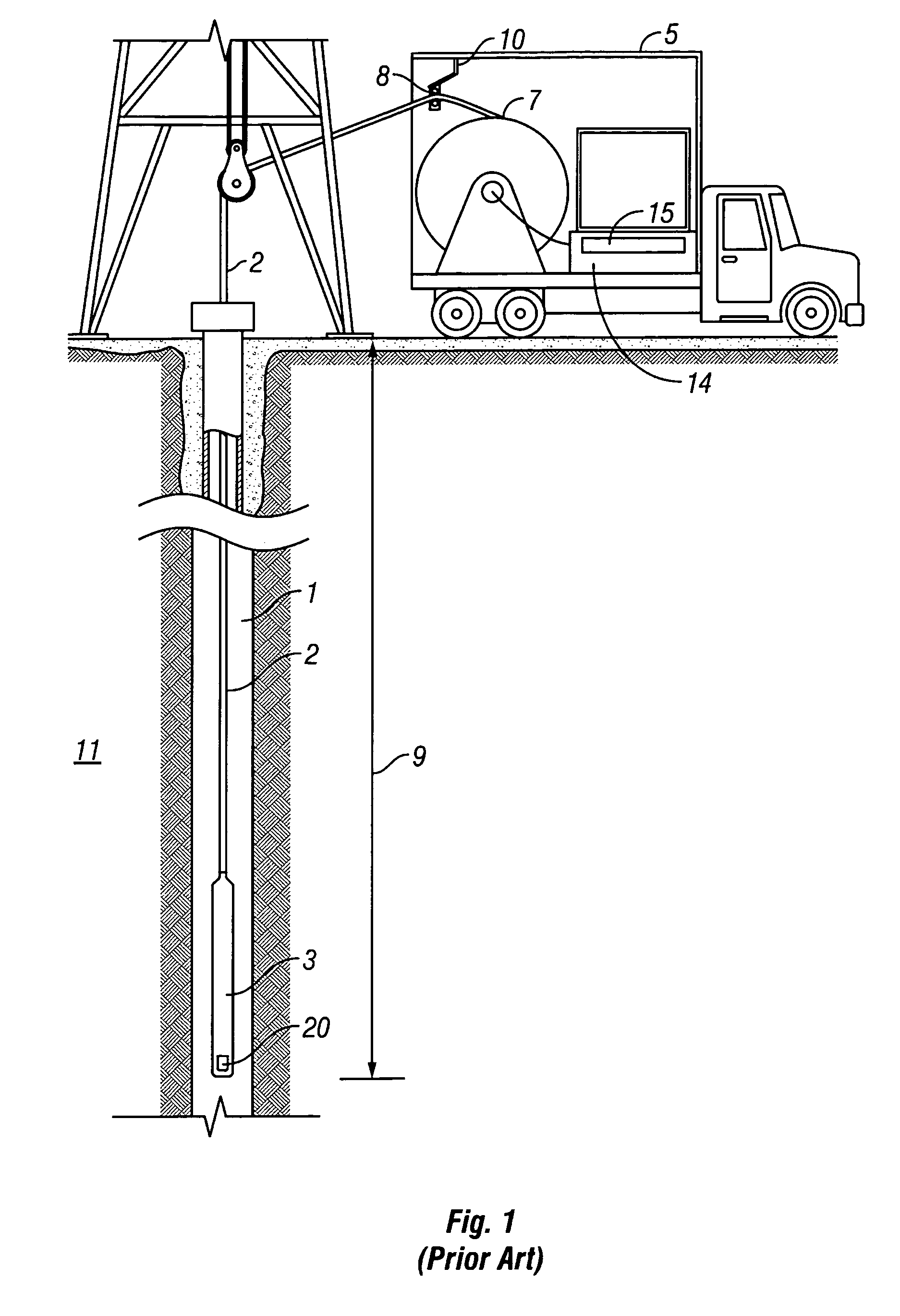
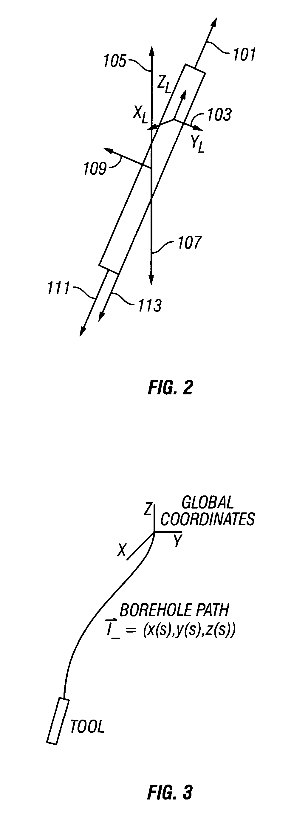
[0029]FIG. 1 shows a well logging instrument 3 as it is typically disposed in a wellbore 1 for recording a well log. The instrument 3 is attached to one end of an armored electrical logging cable 2. The cable 2 is extended into and withdrawn from the wellbore 1 using a winch 7 forming part of a surface logging unit 5. As the cable 2 is unspooled from the winch 7, it passes through a measuring head 8 suspended from a spooling arm 10 attached to the logging unit 5. The measuring head 8 can include an encoder (not shown) for measuring the length of cable 2 unspooled from the drum 7 as it passes the measuring head 8. A well log is typically conducted by first unspooling the cable 2 into the wellbore 1 and then respooling the cable 2 onto the drum 7 while causing the instrument 3 to make measurements corresponding to various properties of formations 11 penetrated by the wellbore 1 as the instrument is correspondingly pulled out of the wellbore 1. The encoder (not shown) on the measuring ...


PUM


Abstract

Wireline depths are estimated using cable depth measurements and accelerometer depth measurements made over a time interval encompassing the time for which the wireline depth is being estimated. A least squares smoothing filter or a weighted least squares smoothing filter may be used. Problems caused by washouts in the borehole are also addressed.

Description

BACKGROUND OF THE INVENTION[0001]1. Field of the Invention[0002]The present invention relates generally to apparatus and methods for determining the “true” depth of a well logging tool suspended from a cable inside a wellbore. This may be done while the cable is being raised or lowered inside a well bore. The method is based on processing of accelerometer measurements.[0003]2. Description of the Related Art[0004]Electric wireline well logging instruments are typically inserted into and withdrawn from wellbores by means of armored electrical cables. The logging instruments generate signals which are related to physical properties of the earth formations through which the wellbore is drilled. A record of the properties of the earth formations with respect to depth in the wellbore is generally made at the earth's surface by pulling the logging instrument out of the wellbore by reeling the cable onto a winch or similar spooling device, while simultaneously recording the signals generate...

Claims


Application Information

Patent Timeline
Patent Type & Authority Patents(United States)
IPC IPC(8): G01V1/40G06F19/00
CPCG01V9/00
Inventor EDWARDS, CARL M.
Owner BAKER HUGHES HLDG LLC
Learn More