Thermoacoustic device

a technology of thermoacoustic devices and refrigeration pumps, which is applied in the direction of mechanical vibration separation, machines/engines, lighting and heating apparatus, etc., can solve the problems of not having a large-scale commercial success of stirling engines and refrigerators, and the efficiency approach to power production or refrigeration has not yet become commercially viable in most applications. to achieve the effect of suppressing gedeon streaming

Inactive Publication Date: 2006-12-05
PENN STATE RES FOUND
View PDF61 Cites 29 Cited by
  • Summary
  • Abstract
  • Description
  • Claims
  • Application Information

AI Technical Summary

Benefits of technology

[0042]The present invention provides a thermoacoustic device with a thermal core including a regenerator or other thermal storage medium sandwiched between first and second heat exchangers. A main volume is preferably defined by a compliant enclosure and is in fluid communication with one of the heat exchangers. A piston forms part of the compliant enclosure and oscillates so as to change the volume in the enclosure. A second multiplier chamber is in fluid communication with the other heat exchanger and also has an oscillatory member for oscillating the volume in the multiplier chamber. The piston and the oscillating member move approximately in phase with one another such that the pressure introduced to the chambers rises at approximately the same time and approximately in phase with one another. Using a thermoacoustic Stirling effect, the oscillating pressure waves pump heat from one of the heat exchangers to the other. Alternatively, heat may be provided to one of the heat exchangers and power extracted by attaching the piston to an alternator or some other means to produce electricity or by attaching the piston to some other device thereby providing energy in the form of reciprocating mechanical motion.

Problems solved by technology

Commercial Failure of the Stirling Cycle
Although an ideal Stirling engine or refrigerator could (in principle) exhibit Carnot performance, neither Stirling engines nor refrigerators ever achieved large-scale commercial success.
There are several reasons why this efficient approach to power production or refrigeration has not yet become commercially viable in most applications.
The fundamental reason is that the improved efficiency (and more recently, the reduced environmental impact) of Stirling cycle devices was not an adequate incentive for its widespread adoption because the additional complexity and associated capital cost of the heat exchangers required by the Stirling cycle was not economically justified.
Although the Rankine cycle is less efficient than an ideal Stirling cycle, the additional mechanical complexity of a Stirling refrigerator and the cost of the heat exchangers needed for Stirling cycle refrigeration was, again, not economically justified.
Thus far, none of these improvements have been sufficient to warrant the replacement of either the internal combustion engine or the vapor-compression refrigeration process by devices using a Stirling cycle.
One drawback to the Swift, Backhaus & Gardner approach for either a thermoacoustic-Stirling engine or refrigerator is that their acoustic network creates a toroidal flow path that includes the regenerator and its associated heat exchangers.
Acoustically induced streaming flow was deemed to be so detrimental for engine performance, the Los Alamos Thermoacoustics Group, headed by Dr.
In addition to the possibility of steady flow through the regenerator, another drawback to the thermoacoustic devices of Swift, et al. is the use of a column of gas to provide the inertance element (4 in FIG. 1), that forms a Helmholtz resonant “acoustic phasing network,” in conjunction with the gas stiffness that functions as compliance element 5.
The oscillatory gas flow through the inertance element generates three types of hydrodynamic dissipation, which reduces the overall efficiency of the heat pumping process.
At the high amplitudes required for commercially acceptable volumetric power density, there are also exit-entrance losses at both ends of inertance tube 4.
The “minor losses” at the inertance tube exit and entrance constituted a loss of 10% of the total input power.
During testing of TRITON, the dissipation of acoustic power associated with the high-velocity oscillatory gas motion, particularly though the neck of the Helmholtz resonator and through the transitions between the neck and the two “bulbs,” led to unacceptably large nonlinear hydrodynamic losses.
These hydrodynamic losses produced a substantial reduction in the overall performance of that refrigeration unit.

Method used


Image

  • Thermoacoustic device
  • Thermoacoustic device
  • Thermoacoustic device

Examples


unfolded embodiment

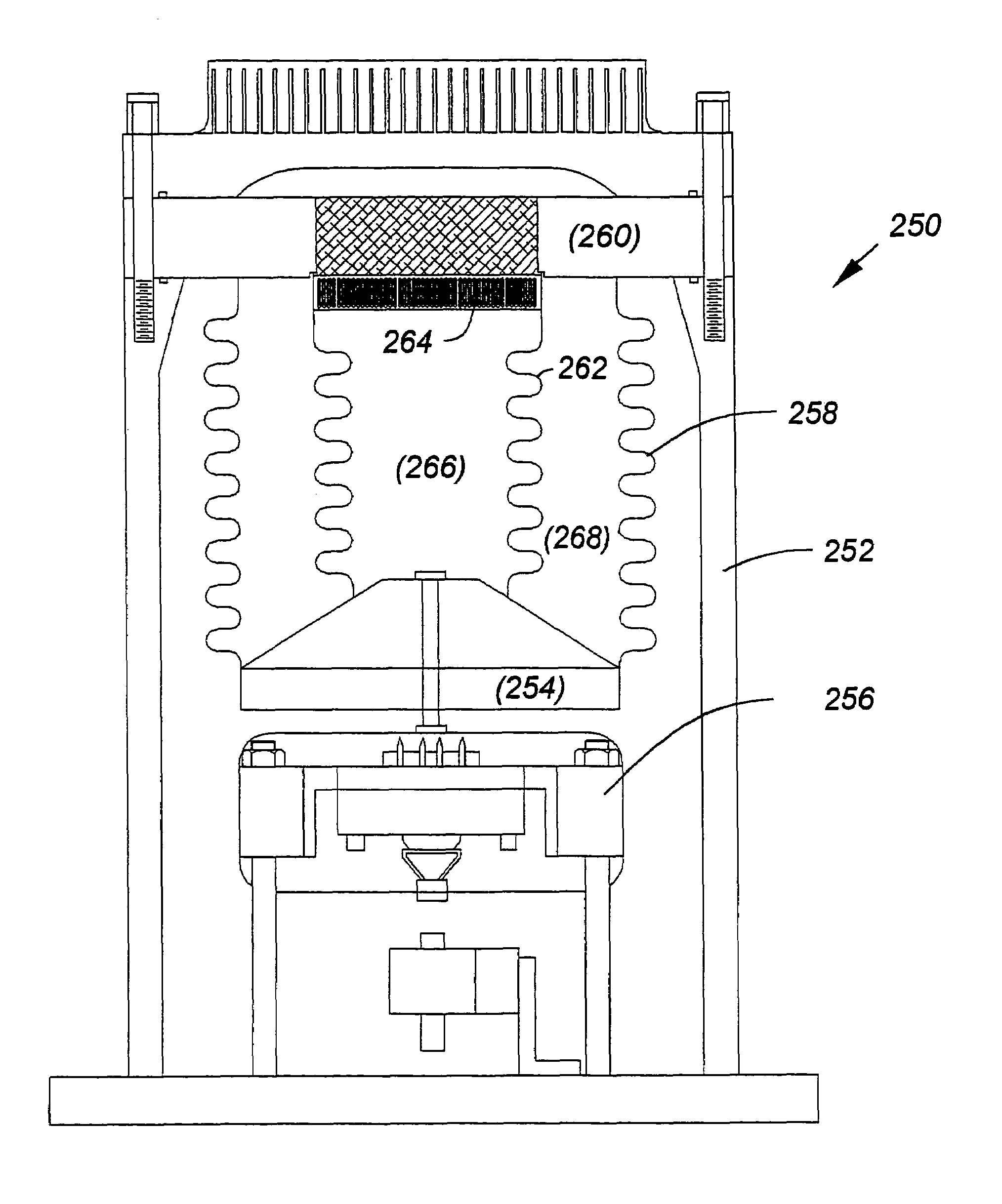
[0120]FIG. 15 provides a thermoacoustic device 280 wherein the multiplier volume 282 is not positioned between the piston 284 and the support 286. Instead, the multiplier volume 282 is on the other side of the support 286. As shown, the device 280 has a pressure vessel 288 with a linear motor 290 positioned in the lower end. The linear motor oscillates the power piston 284, which is a clearance seal design, with a clearance seal 292 at the perimeter of the piston 284. Alternatively, a compliant enclosure design may be used, wherein a bellows extends between the piston 284 and the support 286. Passages 294 are defined through the support 286 to allow fluid communication between the upper and lower halves of the device 280. The multiplier volume 282 is housed inside of a multiplier cylinder 296 that is closed at its upper end by a multiplier piston 298. The hot heat exchanger at 300 is adjacent to, and may be housed in, the multiplier volume 282. As shown, the hot heat exchanger may b...


PUM


Abstract

A thermocoustic device includes a housing with a thermal core supported in the housing and having a first and a second surface. The thermal core includes a first heat exchanger defining the first surface of the thermal core and a second heat exchanger defining the second surface of the thermal core. A main chamber is in fluid communication with the first surface of the thermal core and a secondary multiplier chamber is in fluid communication with the second surface of the thermal core. A working volume of a gaseous working fluid fills the main chamber, the multiplier chamber, and the thermal core at a pressure. An equilibrium pressure is defined as the pressure of the working volume of gaseous working fluids with the thermoacoustic device is in a non-operating mode. The main chamber includes a first oscillating member that is operable when the thermoacoustic device is in an operating mode to oscillate such that the pressure in both the main chamber and in the multiplier chamber is oscillated between a peak pressure greater than the equilibrium pressure and a minimum pressure less than the equilibrium pressure. A main pressure amplitude is defined as one-half of the difference between the peak pressure and the minimum pressure in the main chamber. The secondary multiplier chamber includes a second oscillating member that is operable when the thermoacoustic device is in the operating mode to oscillate such that the pressure in the multiplier chamber is oscillated between a peak pressure greater than the equilibrium pressure and a minimum pressure less than the equilibrium pressure. A multiplier pressure amplitude is defined as one-half of the difference between the peak pressure and the minimum pressure in the multiplier chamber. The first and second oscillating members oscillate at substantially the same frequency and such that the pressure oscillations in the main chamber and the multiplier chamber are substantially in phase with each other. The multiplier pressure amplitude is greater than the main pressure amplitude.

Description

REFERENCE TO RELATED APPLICATIONS[0001]This patent application is a continuation of U.S. patent application Ser. No. 10 / 410,492, filed Apr. 9, 2003 now U.S. Pat. No. 6,725,670, which claims benefit from U.S. provisional patent application Ser. Nos. 60 / 372,008, filed Apr. 10, 2002; 60 / 371,967, filed Apr. 10, 2002; and 60 / 445,866, filed Feb. 6, 2003, the contents of all of which are incorporated in their entirety herein by reference.FIELD OF THE INVENTION[0002]The present invention relates generally to thermoacoustic devices and, more specifically, to thermoacoustic engines and refrigeration pumps. However, the present invention has applicability outside the field of thermoacoustics, and is therefore not limited to thermoacoustic devices.BACKGROUND OF THE INVENTION[0003]During the past two decades, there has been an increasing interest in the development of thermoacoustical cooling engines (pumps) for a variety of commercial, military and industrial applications. Interest in thermoaco...

Claims


Application Information

Patent Timeline
Patent Type & Authority Patents(United States)
IPC IPC(8): F25B9/00B06B1/04F02G1/043F03G7/00F25B9/14H04R31/00
CPCF02G1/0435F03G7/002F25B9/145F02G2243/54F25B2309/001F25B2309/1404F25B2309/1407
Inventor SMITH, ROBERT W. M.POESE, MATTHEW E.WAKELAND, RAY S.GARRETT, STEVEN L.
Owner PENN STATE RES FOUND
Why Eureka
Try Eureka