Electric locking device

a technology of electric locking and pins, which is applied in the direction of positioning apparatuses, metal-working machine components, manufacturing tools, etc., can solve the problems of difficult to adapt to a small pin clamping device with a short stroke, and achieve the effects of saving operating time, simple structure and large clamping for

Active Publication Date: 2006-12-05
SMC CORP
View PDF3 Cites 12 Cited by
  • Summary
  • Abstract
  • Description
  • Claims
  • Application Information

AI Technical Summary

Benefits of technology

[0005]Therefore, it is an object of the present invention to provide an electric locking device having a simple structure and conducting an operation suitable for a pin clamp by using the first and second cams.
[0006]It is another object of the invention to provide an electric locking device in which the speed of operation of a clamping arm up to the time immediately before clamping is increased to save operating time and a clamping force sufficient for clamping operation can be exerted.
[0007]It is another object of the invention to provide an electric locking device which can reliably clamp workpieces of various sizes and a clamping force of which is stable.
[0016]According to the electric locking device having the above structure, if the first and second cams are driven through the speed reducing mechanism by driving of the electric motor, the driven rod is driven in the clamping or clamping releasing direction by the first and second cam contacting members. In other words, the first cam drives the driven rod in the clamping direction through the first cam contacting member and the second cam drives the driven rod in the returning direction through the second cam contacting member. Therefore, it is possible to provide the clamp stroke required for operation and the return stroke for returning to an original position to the clamping arm.
[0017]Moreover, by properly setting a shape of the cam face, it is possible to move the driven rod at a high speed until the clamping arm reaches the vicinity of the end of the clamp stroke so as to save the operating time and to move the driven rod at a low speed when the clamping arm has reached the vicinity of the end so as to obtain the large clamping force. As a result, with a simple structure using the first and second cams, it is possible to provide operations suitable for pin clamping to the clamping arm and to clamp the workpiece with a large force even by using a small and low-power electric motor.
[0018]In the electric locking device, the clamp spring is disposed in the arm driving rod so that size variations and the like of the workpieces to be clamped can be absorbed by the clamp spring. As a result, the workpiece can reliably be clamped with the stable clamping force.

Problems solved by technology

In forming a pin clamping device to meet such requirements by using an electric motor, means for converting a driving force of the electric motor into a linear motion by a gear mechanism and a feed screw mechanism and the like and then transmitting the linear motion transmitted by the feed screw mechanism to a clamping arm through a toggle linkage is difficult to adapt to a small pin clamping device with a short stroke.

Method used


Image

  • Electric locking device
  • Electric locking device
  • Electric locking device

Examples


Embodiment Construction

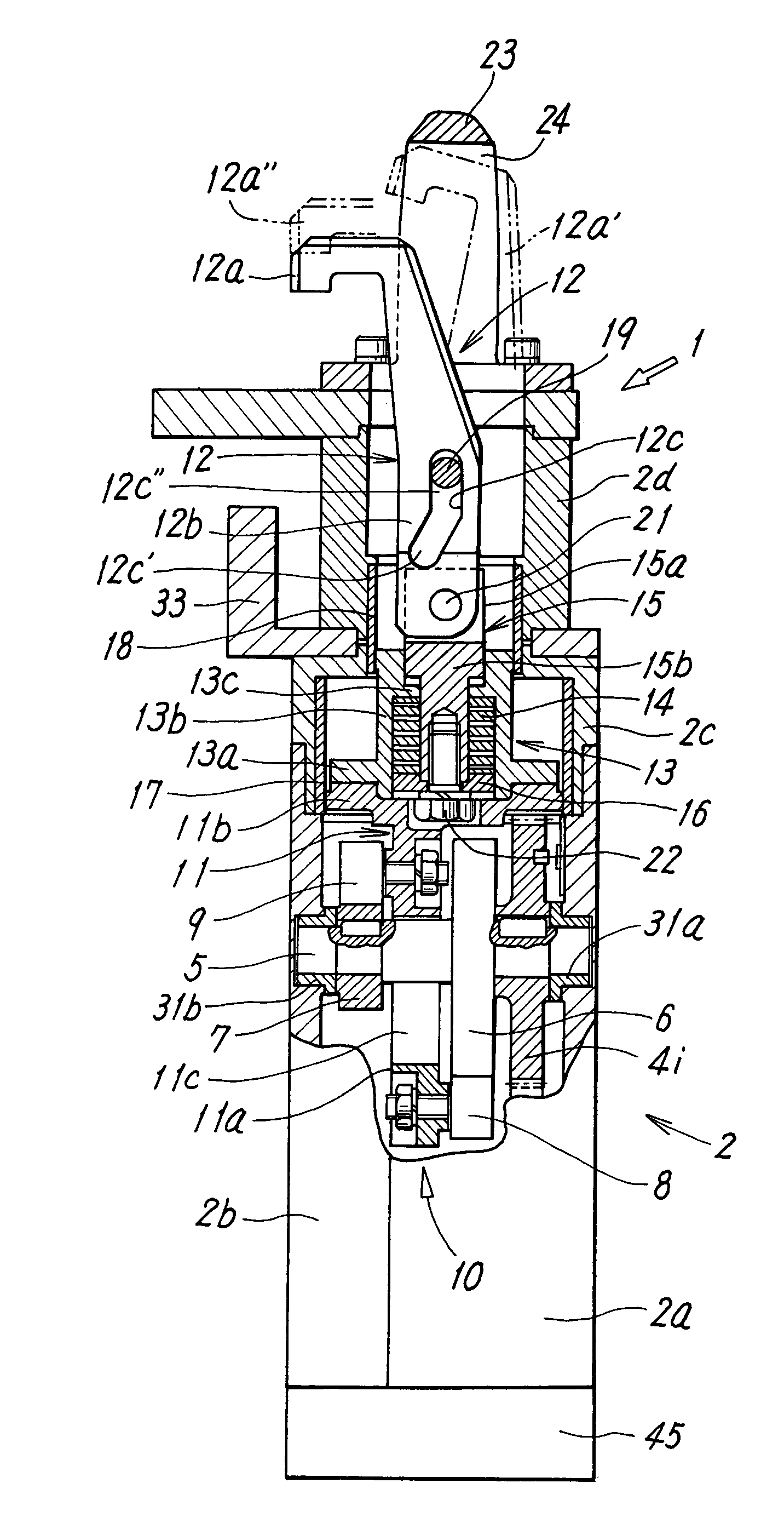
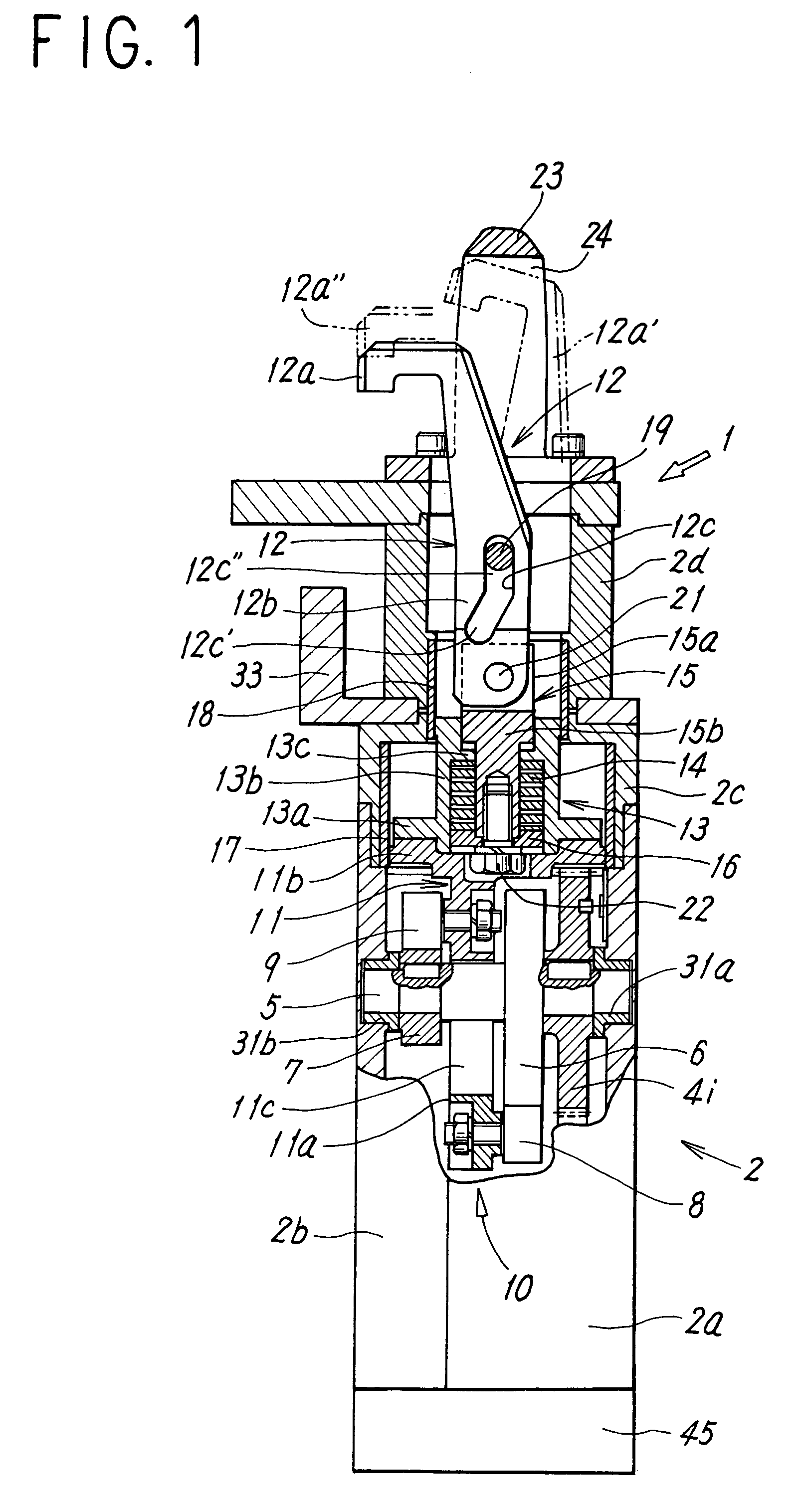
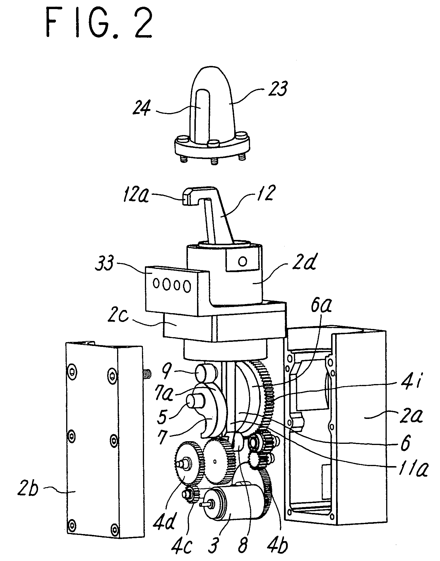
[0029]The drawings show a pin clamping device as an embodiment of an electric locking device according to the present invention. As shown in FIGS. 1 to 5, the electric pin clamping device 1 includes a body 2 forming an outer shell of the device, a speed reducing mechanism 4 housed in the body 2 and formed of a plurality of spur gears 4a to 4i engaged in order as can be seen from FIGS. 3 and 4 to reduce the speed of rotation of an electric motor 3, a camshaft 5 formed of a shaft of a last-stage spur gear 4i in the speed reducing mechanism 4, a first cam 6 and a second cam 7 fixed to the camshaft 5 by key coupling and conjugate with each other, a first cam contacting member 8 and a second cam contacting member 9 respectively in contact with cam faces 6a and 7a of the first and second cams 6 and 7 to convert rotational motions of the first cam 6 and the second cam 7 into linear motions in the same direction, an arm driving rod 10 formed of a driven rod 11 and a connecting rod 15, the d...


PUM


Abstract

The present invention provides an electric locking device which has a simple structure, with which an operating time can be saved, and which has a sufficient clamping force required for operation. To a camshaft coupled to an electric motor through a speed reducing mechanism, a first cam and a second cam conjugate with each other are coupled. The first cam drives an arm driving rod in a clamping direction and the second cam drives the arm driving rod in a returning direction. Rotational motions of the first and second cams are converted into linear motions in the same direction by first and second cam contacting members supported by the arm driving rod. The arm driving rod drives a clamping arm to cause the arm to carry out a clamping operation. A cam face is provided as to move the clamping arm at a high speed until the arm reaches a vicinity of an end and to move the arm at a lower speed after the arm has reached the vicinity of the end.

Description

TECHNICAL FIELD OF THE INVENTION[0001]The present invention relates to a small electric locking device with a short stroke which is used for a clamp such as a pin clamp, a pin locator, a pin ejector, a pallet holder, and a gripper.DESCRIPTION OF THE PRIOR ART[0002]There are pin clamping devices as disclosed in Japanese Utility Model Application Laid-open No. 7-42676 and the like. Although this type of pin clamping device has a short stroke, a pin clamp head is required to approach a workpiece or the like as quickly as possible to shorten the time required for clamping and is required to then slow down at the time of clamping to generate the necessary clamping force.[0003]In forming a pin clamping device to meet such requirements by using an electric motor, means for converting a driving force of the electric motor into a linear motion by a gear mechanism and a feed screw mechanism and the like and then transmitting the linear motion transmitted by the feed screw mechanism to a clamp...

Claims


Application Information

Patent Timeline
Patent Type & Authority Patents(United States)
IPC IPC(8): B23Q3/08B25B5/08
CPCB25B5/08B25B5/087
Inventor ZHAO, KAIRUDAITIS, ERICKUCHIDA, DAVID KENKOZLOWSKI, JEFFREY GERALD
Owner SMC CORP
Why Eureka
Try Eureka