
System for distributing load over multiple servers at an internet site

a technology of distributing load and servers, applied in the direction of data switching networks, coupling device connections, instruments, etc., can solve the problems of affecting the responsiveness of the machine, and ensuring that incoming requests are routed to the servers best able to handle such requests

Inactive Publication Date: 2006-12-05
CISCO TECH INC
View PDF28 Cites 39 Cited by
  • Summary
  • Abstract
  • Description
  • Claims
  • Application Information

AI Technical Summary

Benefits of technology

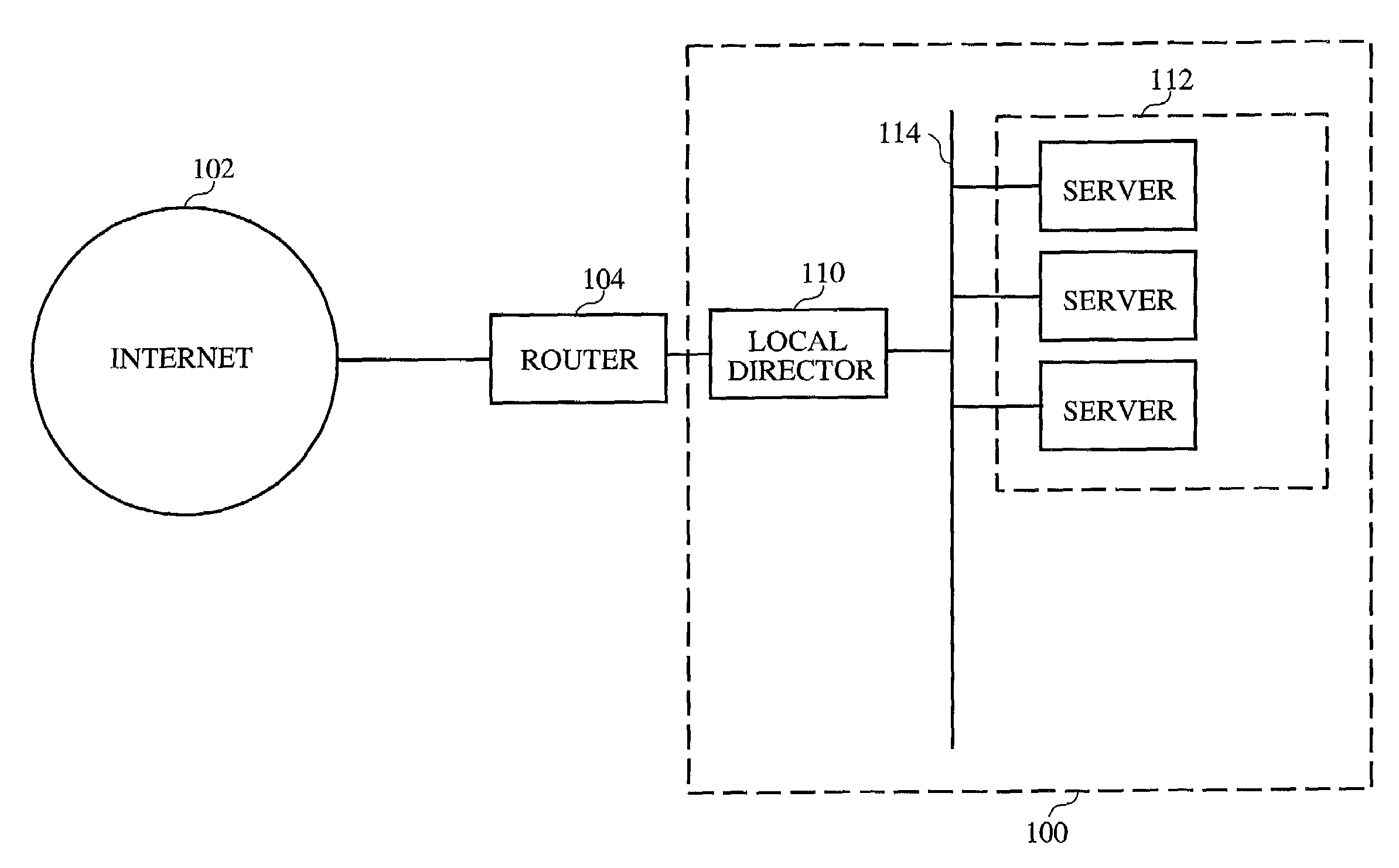
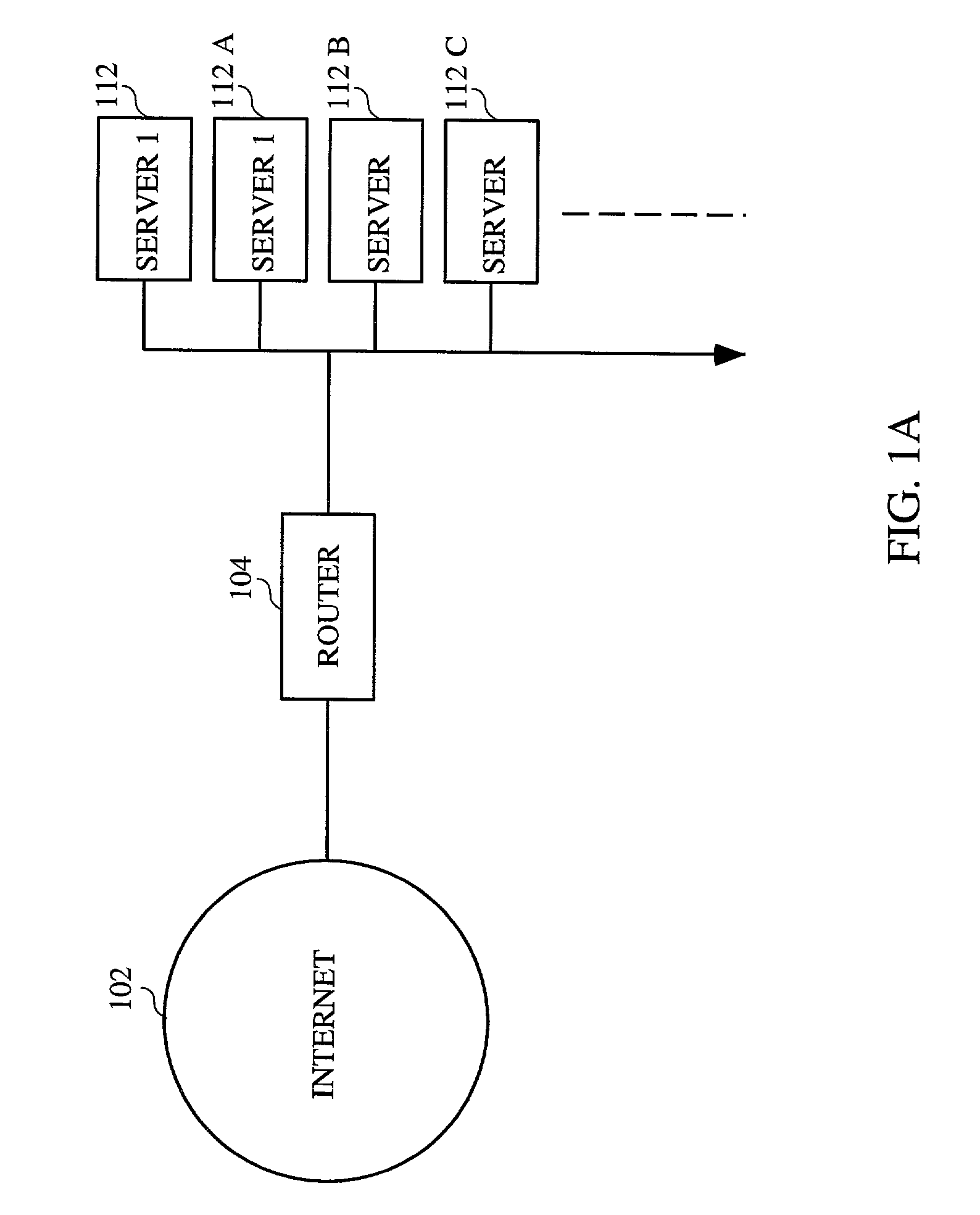
[0015]The present invention provides a system and method for distributing connections among a plurality of servers at an Internet site. All connections are made to a single IP address and a local director selects the server from among the plurality of servers which is to receive the connection. Thus, the DNS server is not relied upon to distribute connections, and the connection distribution scheme i

Problems solved by technology

While this technique does help distribute a site's traffic load over a plurality of servers, it certainly does not guarantee that incoming requests will be routed to the servers best able to handle such requests.
Therefore, a given machine in the round robin rotation may become excessively loaded with connections due to its own lack of capacity or the greater requirements of certain of its connections compared to connections made to other machines in the round robin rotation.
The excess loading on an individual machine may negatively effect responsiveness of the machine.
In such a case, this will result in excessive time delays by this machine whenever data is requested from it.
A technique known as “DNS caching” creates another problem for round robin DNS.

Method used


Image

  • System for distributing load over multiple servers at an internet site
  • System for distributing load over multiple servers at an internet site
  • System for distributing load over multiple servers at an internet site

Examples


Embodiment Construction

[0037]The basic problem of networking a set of devices has been divided into layers. The bottom layer is a physical layer. It handles the actual physical connections between devices. The second layer is the data link layer. It describes how the data is formatted which is on the physical medium which connects the devices. The third layer is the network layer. It handles cases where there is greater than one connection per machine. The fourth layer is the transport layer. This determines that all of the messages from a source reach the destination reliably and in an unduplicated fashion. The second layer is subdivided into a Logical Link Control (“LLC”) layer and a Media Access Control (“MAC”) layer. A MAC address is required in this layer. In the TCP / IP suite of protocols employed on the Internet, the third layer or network layer is the IP layer. This layer requires a globally unique IP address in order to route packets to the right physical machine. The IP address is issued by a cen...


PUM


Abstract

Disclosed is a system and method for distributing connections among a plurality of servers at an Internet site. All connections are made to a single IP address and a local director selects the server from among the plurality of servers which is to receive the connection. Thus, the DNS server is not relied upon to distribute connections, and the connection distribution scheme is not avoided when DNS is bypassed. In one embodiment, a session distribution scheme is implemented such that connections are distributed to the server in the group of servers which has the fewest connections of the group. In other embodiments, other session distribution schemes which route connections based on the predicted response times of the servers or according to a round robin scheme are used.

Description

CROSS REFERENCE TO RELATED APPLICATIONS[0001]This application is a continuation application of U.S. application Ser. No. 08 / 850,248 filed May 2, 1997, now U.S. Pat. No. 6,317,775, which is a continuation-in-part application of U.S. application Ser. No. 08 / 552,807 filed Nov. 3, 1995, now U.S. Pat. No. 5,793,763, which is incorporated herein by reference for all purposes.[0002]This application is related to application Ser. Nos. 08 / 850,730 and 08 / 850,836, filed concurrently herewith and subsequently issued as U.S. Pat. No. 6,061,349 issued May 9, 2000 and No. 6,104,717 issued Aug. 15, 2000, respectively, which are incorporated herein by reference for all purposes.BACKGROUND OF THE INVENTION[0003]The present invention relates to methods and apparatus for simulating a virtual server by distributing connection requests over multiple servers at an Internet site. More specifically, the invention relates to methods and apparatus for monitoring the availability of servers at an Internet site...

Claims


Application Information

Patent Timeline
IPC IPC(8): G06F15/173G06F15/16G06F11/20H01R31/00H04L69/40
CPCH01R31/005H04L12/24H04L29/06H04L29/12009H04L29/12367H04L29/125H04L29/12924H04L41/00H04L61/2514H04L61/2564H04L61/6063H04L63/0254H04L67/1008H04L67/1002H04L69/40H04L67/1017H01R2201/04H04L61/00H04L2101/663H04L67/1001H04L9/40
Inventor COILE, BRANTLEY W.HOWES, RICHARD A.KERSEY, EDWARD C.TENEREILLO, PETER A.
Owner CISCO TECH INC
Learn More