Use of downhole high pressure gas in a gas-lift well and associated methods

a high-pressure gas and gas-lifting technology, which is applied in the direction of survey, sealing/packing, borehole/well accessories, etc., can solve the problems of determining the production cost and the well being taken out, and achieve the effects of reducing costs, simplifying installation procedures, and reducing costs

Inactive Publication Date: 2006-12-12
SHELL OIL CO
View PDF141 Cites 193 Cited by
  • Summary
  • Abstract
  • Description
  • Claims
  • Application Information

AI Technical Summary

Benefits of technology

[0021]The present invention provides systems and methods to use reservoir gas for lifting oil from the oil bearing zones. The systems and methods of the present invention replace or supplement the use of compressed gas supplied by surface equipment. Such replacement or supplementing is likely much less costly and more environmentally desirable than merely supplying compressed gas with surface equipment.
[0022]The Related Applications describe alternative ways to provide electrical power from the surface to downhole devices, and to establish bi-directional communications for data and commands to be passed between the surface and downhole devices using surface and downhole modems. The preferred embodiment utilizes the production tubing and the well casing as the electrical conduction paths between the surface and downhole equipment. The cost reduction and simplification of installation procedures which accrue from obviating the need for electrical cables to provide power, sensing, and control functions downhole allow wider deployment of active equipment downhole during production.
[0024]In the present invention such downhole devices provide the necessary degree of real-time measurement and control to use downhole high-pressure gas sources for lift. That is, downhole sensors can monitor the operation of the well as the downhole gas sources are routed by controllable valves to lift the oil as needed or desired.

Problems solved by technology

Typically the orifice size of the gas lift valve is preset by selection at the time the valve is installed, and cannot be changed thereafter without changing the valve, which requires that the well be taken out of production.
The ongoing supply of compressed lift gas is a major determinant of production cost.
The cost is a combination of the capital investment to provide the compressors and field infrastructure to convey the gas to each well, and the ongoing operating cost of running the compressors and maintaining them.
Nevertheless, in most situations the naturally-occurring reservoir gas is not used to lift the oil because of the inability to devise a method to monitor and control downhole operations.

Method used


Image

  • Use of downhole high pressure gas in a gas-lift well and associated methods
  • Use of downhole high pressure gas in a gas-lift well and associated methods
  • Use of downhole high pressure gas in a gas-lift well and associated methods

Examples


Embodiment Construction

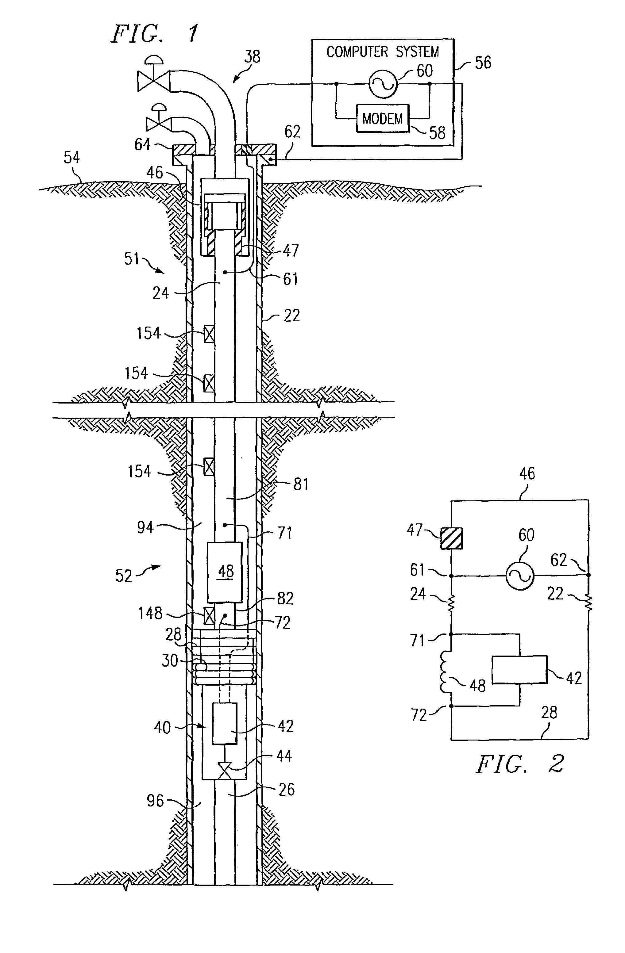
[0031]Referring now to the drawings, wherein like reference numbers are used herein to designate like elements throughout the various views, preferred embodiments of the present invention are illustrated and further described, and other possible embodiments of the present invention are described. The figures are not necessarily drawn to scale, and in some instances the drawings have been exaggerated and / or simplified in places for illustrative purposes only. One of ordinary skill in the art will appreciate the many possible applications and variations of the present invention based on the following examples of possible embodiments of the present invention, as well as based on those embodiments illustrated and discussed in the Related Applications, which are incorporated by reference herein to the maximum extent allowed by law.

[0032]Note that the term “modem” is used herein to generically refer to any communications device for transmitting and / or receiving electrical communication si...


PUM


Abstract

A gas-lift petroleum well and method for producing petroleum products using downhole pressurized gas to provide lift. The gas-lift well having a well casing, a production tubing, a packer, and a gas-lift valve. The well casing extends within a wellbore of the well, and the wellbore extends through oil and gas zones. The production tubing extends within the casing. The tubing having an opening formed therein, which is in fluid communication with an oil zone. The packer is located downhole in the casing and coupled to the tubing. The packer can have an electrically controllable packer valve, which is adapted to control a flow of downhole pressurized gas from one side of the packer to another. The downhole pressurized gas is provided by a gas zone that the wellbore passes through. The downhole gas-lift valve is coupled to the tubing and is adapted to control a flow of downhole pressurized gas into oil in the tubing for lifting the oil. The gas-lift valve can be an electrically controllable valve. The tubing and casing are used as electrical conductors for supplying power and / or communications downhole. The current in the tubing is routed using a ferromagnetic induction choke to create a voltage potential, which provides electrical power to downhole electrical devices. Also, there may be a bypass passageway to route downhole gas to gas-lift valves. There may also be downhole sensors to measure physical quantities (e.g., pressure). Such measurements can be used for feedback control of downhole electrically controllable valves.

Description

CROSS-REFERENCES TO RELATED APPLICATIONS[0001]This application claims the benefit of the following U.S. Provisional Applications, all of which are hereby incorporated by reference:[0002]COMMONLY OWNED AND PREVIOUSLY FILEDU.S. PROVISIONAL Pat. applicationsT&K #Ser. No.TitleFiling DateTH 159960 / 177,999Toroidal Choke Inductor forJan. 24, 2000Wireless Communication andControlTH 160060 / 178,000Ferromagnetic Choke inJan. 24, 2000WellheadTH 160260 / 178,001Controllable Gas-Lift WellJan. 24,2000and ValveTH 160360 / 177,883Permanent, Downhole,Jan. 24,2000Wireless, Two-WayTelemetry Backbone UsingRedundant Repeater, SpreadSpectrum ArraysTH 166860 / 177,998Petroleum Well HavingJan. 24, 2000Downhole Sensors,Communication, and PowerTH 166960 / 177,997System and Method for FluidJan. 24, 2000Flow OptimizationTS 618560 / 181,322A Method and Apparatus forFeb. 9, 2000the Optimal Predistortionof an Electromagnetic Signalin a DownholeCommunications SystemTH 1599x60 / 186,376Toroidal Choke Inductor forMar. 2, 2000Wir...

Claims


Application Information

Patent Timeline
IPC IPC(8): E21B43/12E21B43/00E21B43/14E21B17/00E21B33/129E21B34/06E21B34/08E21B34/16E21B47/12H04B5/00
CPCE21B17/003E21B33/1294E21B34/066E21B34/08E21B34/16E21B43/122E21B43/123E21B43/14E21B47/12E21B47/122E21B47/13
Inventor HIRSCH, JOHN M.STEGEMEIER, GEORGE LEOHALL, JAMES WILLIAMVINEGAR, HAROLD J.BURNETT, ROBERT REXSAVAGE, WILLIAM MOUNTJOYCARL, JR., FREDERICK GORDON
Owner SHELL OIL CO
Why Eureka
Try Eureka