
Wind turbine driven generator system for a motor vehicle

a generator system and motor vehicle technology, applied in the field of vehicles, can solve the problems of reducing the efficiency of the vehicle, and reducing the safety of the vehicle, so as to achieve the effect of not adding to the wind resistance of the vehicl

Active Publication Date: 2006-12-12
MABERRY ROBERT L
View PDF23 Cites 76 Cited by
  • Summary
  • Abstract
  • Description
  • Claims
  • Application Information

AI Technical Summary

Benefits of technology

[0010]An advantage of the present invention is that it does not add to the wind resistance of the vehicle.
[0011]Another advantage is that it does not detract from the aesthetic appeal of the vehicle.

Problems solved by technology

A problem is that the housing that contains the turbine on the roof of the vehicle greatly adds to the vehicle's wind resistance.
The power source that propels the vehicle must produce more power in order to overcome the wind resistance, thereby reducing the efficiency of the vehicle.
Turbine generator units mounted on top of the front hood of the vehicle have the additional disadvantage of obstructing the view of the driver of the vehicle, thereby causing a safety hazard.
Turbine generator units mounted on the roof or front hood of the vehicle have the further disadvantage of being aesthetically unappealing.

Method used


Image

  • Wind turbine driven generator system for a motor vehicle
  • Wind turbine driven generator system for a motor vehicle
  • Wind turbine driven generator system for a motor vehicle

Examples


Embodiment Construction

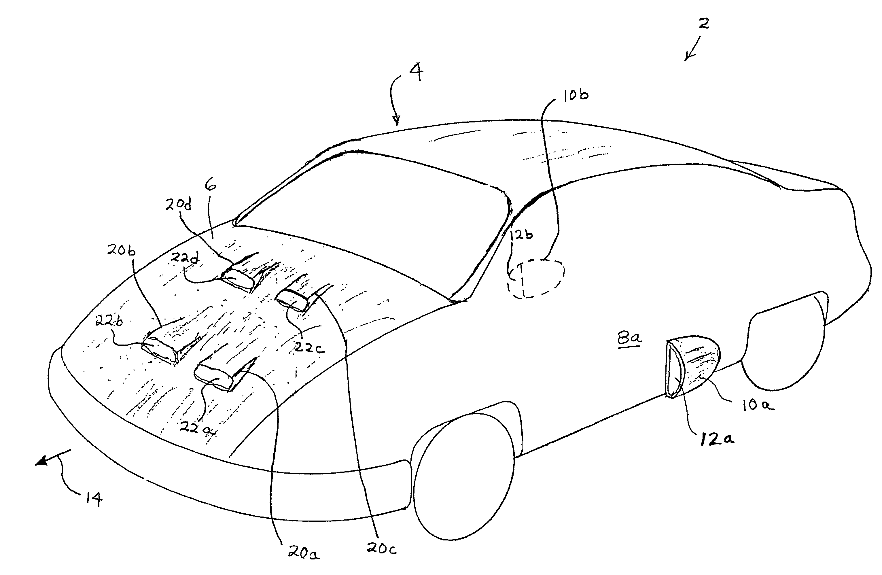
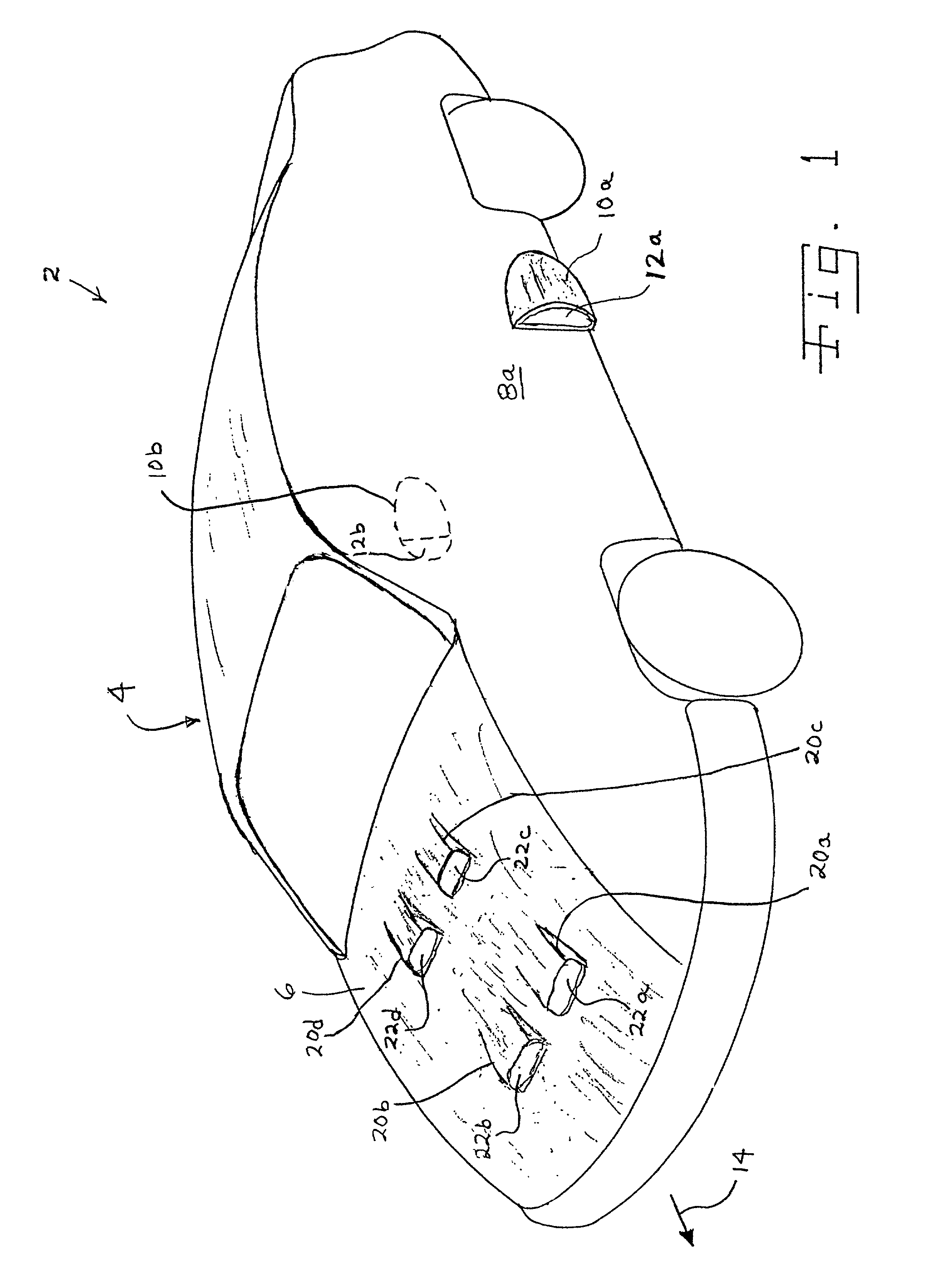
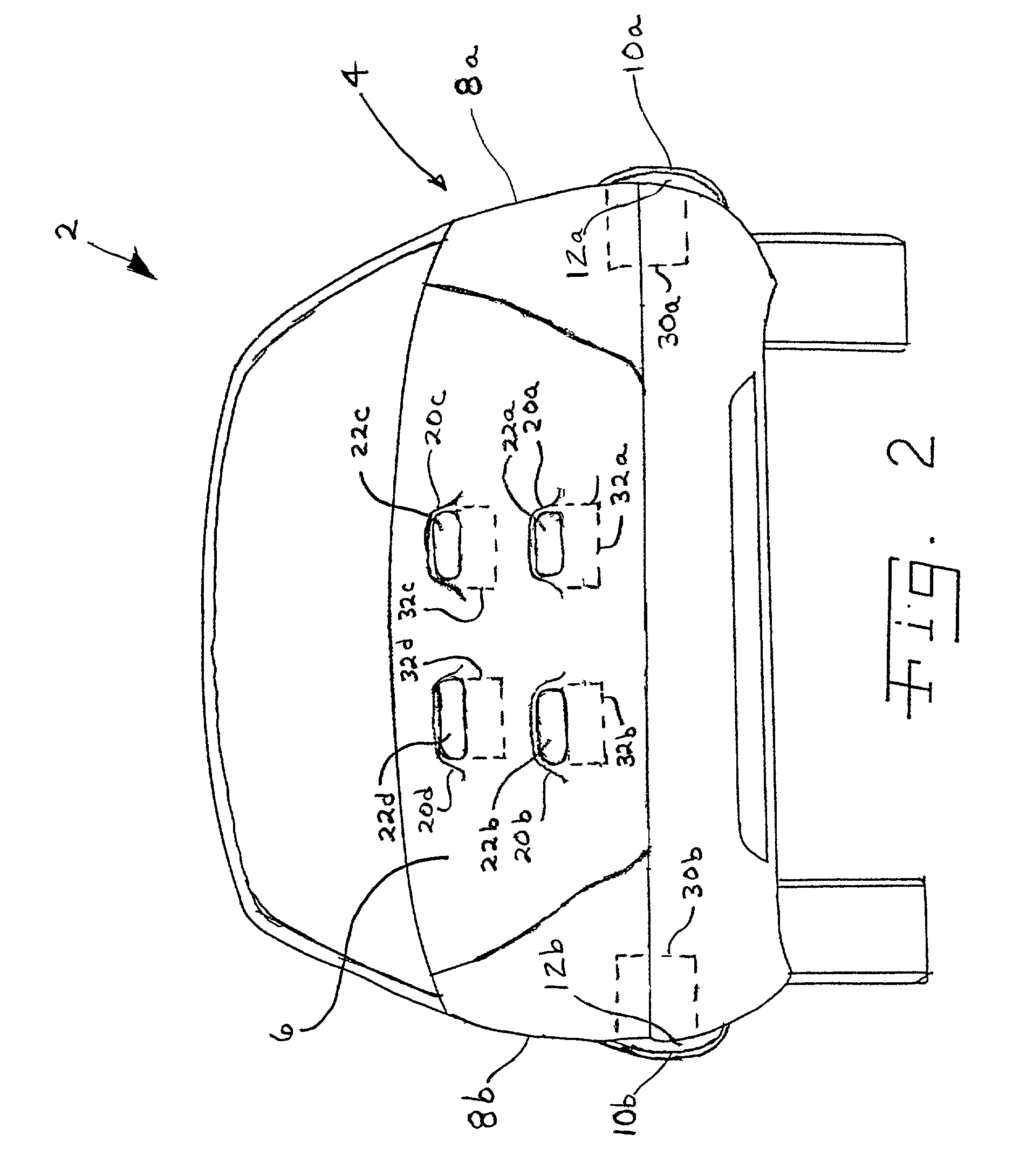
[0020]Referring now to the drawings and particularly to FIG. 1, there is a vehicle 2 embodying the present invention. Vehicle 2 includes a body 4. As shown in FIGS. 1 and 2, body 4 includes a front hood 6, a side panel 8a and a side panel 8b.

[0021]Side panel 8a includes an air guide 10a defining an opening 12a. Side panel 8b includes an air guide 10b defining an opening 12b. Air guides 10a and 10b are oriented to receive an airflow when vehicle 2 is traveling in the direction indicated generally by direction arrow 14. Airflows received in openings 12a and 12b are directed through corresponding openings in side panels 8a and 8b, respectively. It is contemplated that air guide 10a may be formed as an integral portion of side panel 8a, or may be fixedly attached to side panel 8a. Likewise, it is contemplated that air guide 10b may be formed as an integral portion of side panel 8b, or may be fixedly attached to side panel 8b.

[0022]Front hood 6 includes air guides 20a, 20b, 20c and 20d...


PUM


Abstract

The invention relates to a vehicle including a body having a one or more openings. The body is configured, such as through the use of air guides, to receive an airflow through the one or more openings. An electrical generator assembly is mounted inside the vehicle and in fluid communication with a respective opening to receive the airflow, and wherein a separate electric generator assembly is associated with each of the openings. Each electrical generator assembly includes a housing, an electric generator mounted to the housing and a turbine assembly coupled to the electric generator.

Description

BACKGROUND OF THE INVENTION[0001]1. Field of the Invention[0002]The present invention relates to a vehicle, and, more particularly, to a wind turbine driven generator system for a vehicle, such as an automobile.[0003]2. Description of the Related Art[0004]It is known to provide a wind turbine driven generator on a moving vehicle in order to supply electric power for purposes such as recharging a battery or running accessories. Such turbine generator units have been mounted on the roof of the passenger compartment as well as on top of the front hood of the vehicle.[0005]A problem is that the housing that contains the turbine on the roof of the vehicle greatly adds to the vehicle's wind resistance. The power source that propels the vehicle must produce more power in order to overcome the wind resistance, thereby reducing the efficiency of the vehicle. Turbine generator units mounted on top of the front hood of the vehicle have the additional disadvantage of obstructing the view of the...

Claims


Application Information

Patent Timeline
IPC IPC(8): B60K16/00B60L8/00B62D25/10
CPCB60K6/48B60K16/00B62D25/105F03D9/002F03D11/04B60L8/006B60K2016/006F05B2240/941Y02E10/728Y02T10/6221Y02T10/7083Y02T10/90Y02T90/16Y02E10/725F03D9/25F03D9/32F03D13/20Y02E10/72Y02T10/62Y02T10/7072
Inventor MABERRY, ROBERT L.
Owner MABERRY ROBERT L
Learn More