Light source and projector

a technology of light source and projector, which is applied in the field of light source device, can solve the problems of insufficient cooling ability of fans, exploded light-emitting tubes made of quartz glass etc., scattered broken pieces, etc., and achieve the effects of reducing the size of the light source device and the casing, efficient cooling, and simplifying the structur

Inactive Publication Date: 2006-12-12
SEIKO EPSON CORP
View PDF30 Cites 24 Cited by
  • Summary
  • Abstract
  • Description
  • Claims
  • Application Information

AI Technical Summary

Benefits of technology

[0008]An object of the present invention is to provide a light source device capable of preventing the broken pieces of a light source lamp from scattering when the light source lamp is damaged and capable of efficiently introducing the air for cooling the light source lamp toward the inside thereof, and a projector using the light source device.

Problems solved by technology

Further, light-emitting tube made of quartz glass etc. may be exploded according to life span of the lamps and broken pieces thereof may be scattered inside the projector.
However, according to the above arrangement where the air vents are closed by the lid components, since a space for opening and closing the lids have to be secured, a discharge hole of a lamp-cooling fan inside the projector cannot be directly connected with the opening, so that a part of the air outflowed from the discharge hole of the fan is leaked to the other section and the cooling ability of the fan cannot be fully exerted.

Method used


Image

  • Light source and projector
  • Light source and projector
  • Light source and projector

Examples


Embodiment Construction

)

[0030]An embodiment of the present invention will be described below with reference to the attached drawings.

1. Primary Arrangement of Projector

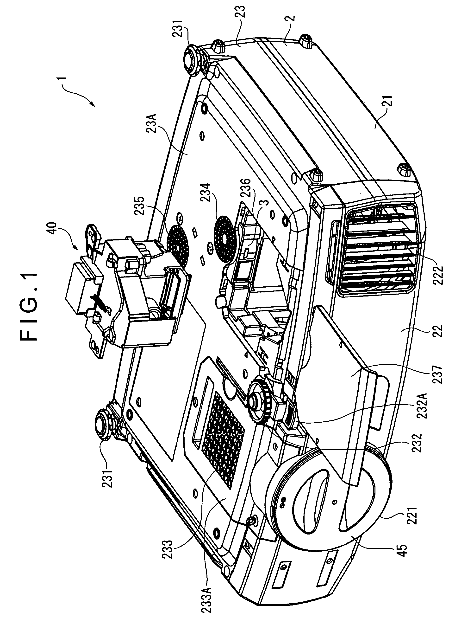
[0031]FIG. 1 is a perspective view showing a lower front side of a projector provided with a light source device according to an embodiment of the present invention.

[0032]A body 1 of the projector has an exterior case 2 (casing) covering the body 1. The exterior case 2 is formed in an approximately rectangular parallelepiped having greater dimension in width direction orthogonal to a light-projecting direction of the below-described projection lens 45 than in the light-projecting direction.

[0033]The exterior case 2 has an upper case 21, a front case 22 and a lower case 23. The upper case 21 forms the upper side, the lateral sides and the rear side of the body 1. The front case 22 forms the front side of the body 1. The lower case 23 forms the bottom side, the lateral sides and the rear side of the body 1. The respective cases 21 to 23 are i...


PUM


Abstract

A light source device (40) attached to an optical equipment provided with a light-source cooling fan (3) has a light source (401), a reflector (402), a light-transmissive component (51) that closes the light-irradiation side of the reflector (402) and a light source housing (50) that houses the above components. An opening (402A) for introducing a cooling air is formed on the reflector (402) and an opening (52) is formed on the light source housing (50) at a position corresponding to the light source housing (50). A duct (53) of which light-irradiation side is opened is provided on the opening (52). When the light source device (40) is attached to the optical equipment, the duct (53) protrudes toward the light-irradiation side to be connected with the fan (3). The opening (52) is opened in accordance therewith, so that the air from the fan (3) is introduced into the reflector (402).

Description

BACKGROUND OF THE INVENTION[0001]1. Field of the Invention[0002]The present invention relates to a light source device. More specifically, the present invention relates to a light source device used in an optical equipment such as a projector using a light beam irradiated by a light source, the light source device capable of efficiently cooling a light source lamp housed therein by introducing an air from a fan provided on the optical equipment.[0003]2. Description of Related Art[0004]Conventionally, projectors have been used for presentation at conferences, academic societies, exhibitions, movie-viewing at home and the like. Such projectors modulate a light beam irradiated by a light source provided inside an exterior case in accordance with image information to form an optical image and projects the optical image in an enlarged manner. In recent projectors, in order to clearly display the projected optical image, it is required to increase the illuminance of light source lamps.[00...

Claims


Application Information

Patent Timeline
Patent Type & Authority Patents(United States)
IPC IPC(8): F21V29/00F21S2/00F21V29/02F21Y101/00G03B21/14G03B21/16G03B21/20H04N5/74
CPCF21V29/02G03B21/16G03B21/145G03B21/2026H04N9/3141F21V29/67F21V29/83
Inventor KATO, HISAMARONISHIZAWA, GAKU
Owner SEIKO EPSON CORP
Why Eureka
Try Eureka