Method and system for calibrating a source and detector instrument

a detector and source technology, applied in the field of source and detector instruments, can solve the problems of perturbation denigration of performance, severe artifacts, and deviations from ideal behavior, and achieve the effects of fast, accurate and generalization

Active Publication Date: 2006-12-12
UNIV HEALTH NETWORK
View PDF12 Cites 62 Cited by
  • Summary
  • Abstract
  • Description
  • Claims
  • Application Information

AI Technical Summary

Benefits of technology

[0010]A direct, non-iterative method is provided herein for determination of pose based on the position of the fiducial markers in a given projection image. The location of markers within the phantom are known with respect to one another. The phantom may be placed arbitrarily with respect to source and detector provided that the fiducial markers are visible in the projection image. A specific embodiment of the invention involves a phantom containing markers, such as metal ball bearings, arranged in two circles, which project as ellipses. By relating the known geometries of the markers and their projection, the location (Xs,Ys,Zs) of the source as well as the location (Xd,Yd,Zd) and orientation (θ,φ,η) of the detector may be ascertained using a direct, non-iterative analysis. This analysis is fast, accurate, and general in that it can completely determine pose from a single projection, allowing complete specification of system geometry for a system in which a single projection is acquired and / or for a system in which the source and detector move in some trajectory about the phantom and acquire one or multiple projections. The resulting pose(s) is completely specified in the reference frame of the phantom, which can in turn be related to other reference frames by appropriate transformations, such as the reference frame of a medical treatment device or any other system utilizing data from the projection system.

Problems solved by technology

Although the integration of imaging systems with delivery systems has many advantages, there is at least one drawback.
When imaging and delivery systems are integrated, motion of the components is less stable than the separate systems, resulting in perturbations from ideal behavior.
Such perturbations denigrate performance.
For example, in cone beam tomography, non-ideal motion, such as tilting or twisting of the image device, can produce severe artifacts, such as loss of detail, poor registration, and streak artifacts.
In the delivery system, perturbations can cause inaccurate delivery of energy to a part of the body.

Method used


Image

  • Method and system for calibrating a source and detector instrument
  • Method and system for calibrating a source and detector instrument
  • Method and system for calibrating a source and detector instrument

Examples


Embodiment Construction

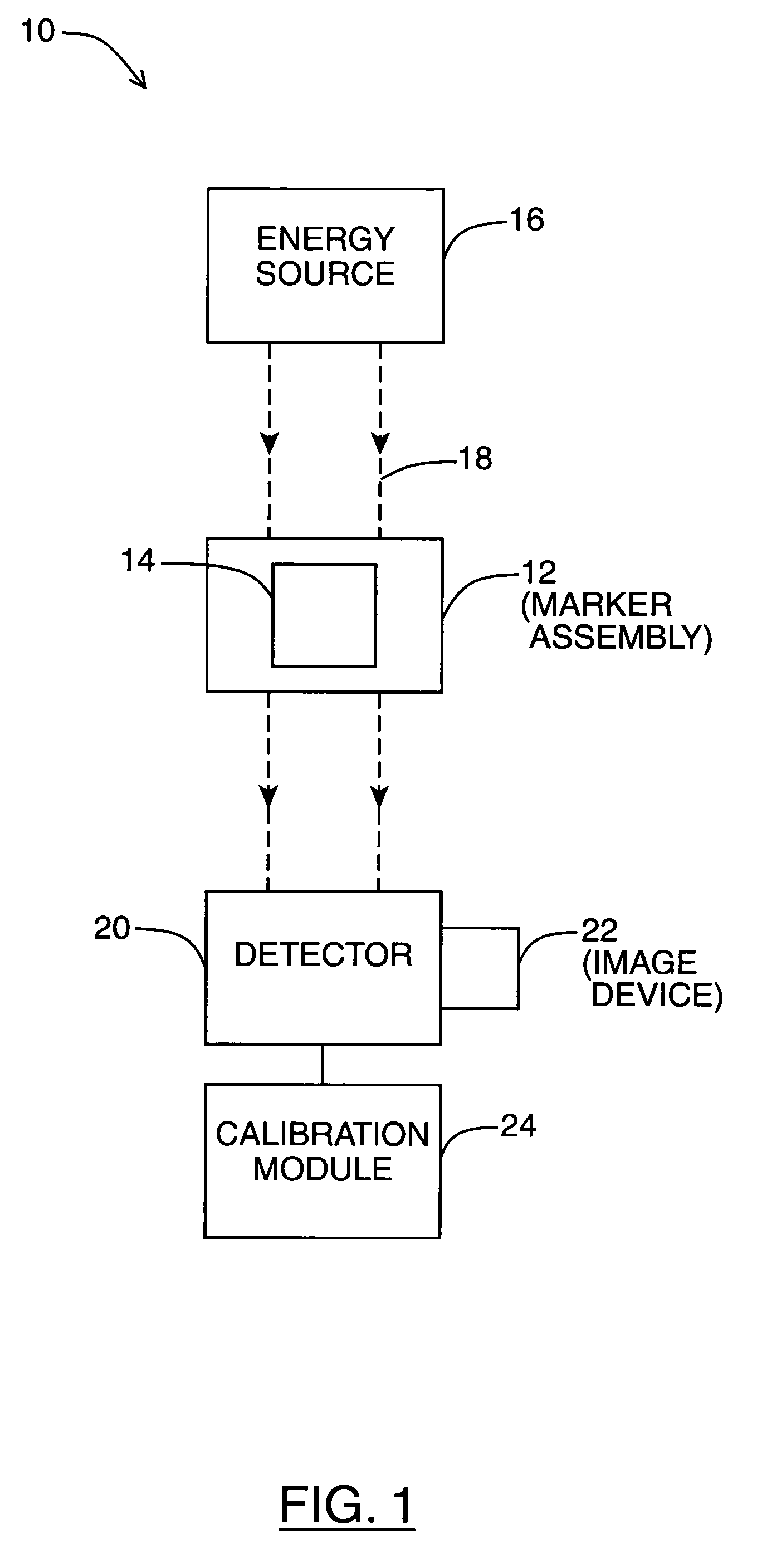
[0034]FIG. 1 shows a box-diagram of a calibration system 10 for calibrating a source and detector instrument. For example, the source and detector instrument can be an imaging instrument used to image a body part, such as a radiography, a stereography, a bi-plane imaging, a fluoroscopy, a tomosynthesis or a tomography instrument.

[0035]The calibration system 10 includes a “phantom” or marker assembly 12 having a plurality of markers 14 whose locations with respect to one another is known. The calibration system 10 further includes an energy source 16 that can emit energy packets 18, a detector 20, an image device 22, and a calibration module 24.

[0036]The energy source 16 targets the plurality of markers 14 with energy packets 18. The energy source 16 can include an x-ray, a gamma ray, an atomic, a sub-atomic, an optical photon, an electromagnetic wave, an x-ray tube, a particle accelerator or a radionuclide source.

[0037]The detector 20 detects energy packets after the plurality of ma...


PUM


Abstract

A system for obtaining coordinate data of a source and detector instrument are described. The system includes a marker assembly having a plurality of markers with a particular geometry, and an energy source for targeting the plurality of markers with energy packets. The system further includes a detector for detecting energy packets after the plurality of markers have interacted therewith, and an image device for forming image data of the plurality of markers from the energy packets detected by the detector. A calibration module for utilizes the particular geometry of the plurality of markers and the image data to non-iteratively determine coordinate data.

Description

CROSS-REFERENCE TO RELATED APPLICATION[0001]The instant application claims priority to Provisional Application No. 60 / 493,953, filed Aug. 8, 2003, whose contents are incorporated herein by reference.FIELD OF THE INVENTION[0002]The invention relates to source and detector instruments, and more specifically to calibrating such instruments.BACKGROUND OF THE INVENTION[0003]Volumetric imaging has become an integral part of modern medicine. Such imaging has been widely used to not only diagnose disease but as an aid in administering medical treatments. When using diagnostic probes, operating instruments or radiation therapy, a medical professional can be greatly aided by images taken of the patient that can identify target areas, or areas to be avoided.[0004]For example, cone-beam computed tomography (CBCT) instruments have been coupled to X-ray delivery devices to provide in situ clinical imaging and radiation therapy simultaneously. The Elekta Synergy™ system is an example of a commerci...

Claims


Application Information

Patent Timeline
Patent Type & Authority Patents(United States)
IPC IPC(8): G01D18/00H05G1/28A61B6/00A61N5/10
CPCA61B6/547A61B6/583A61B6/585A61B6/587A61N5/1049A61B6/027A61B6/4071A61N2005/1061A61B6/584
Inventor CHO, YOUNG-BINMOSELEY, DOUGLAS J.SIEWERDSEN, JEFFREY H.JAFFRAY, DAVID A.
Owner UNIV HEALTH NETWORK
Why Eureka
Try Eureka