
Endodontic instrument

a technology of endodontic instruments and endodontic fillings, applied in the field of endodontic instruments, can solve the problems of reducing the effectiveness of endodontic instruments, reducing the friction between the file and the tooth, and making instruments, so as to reduce the amount of friction generated within the canal, and reduce the effect of friction within the canal

Inactive Publication Date: 2006-12-12
ORMCO CORP
View PDF10 Cites 20 Cited by
  • Summary
  • Abstract
  • Description
  • Claims
  • Application Information

AI Technical Summary

Benefits of technology

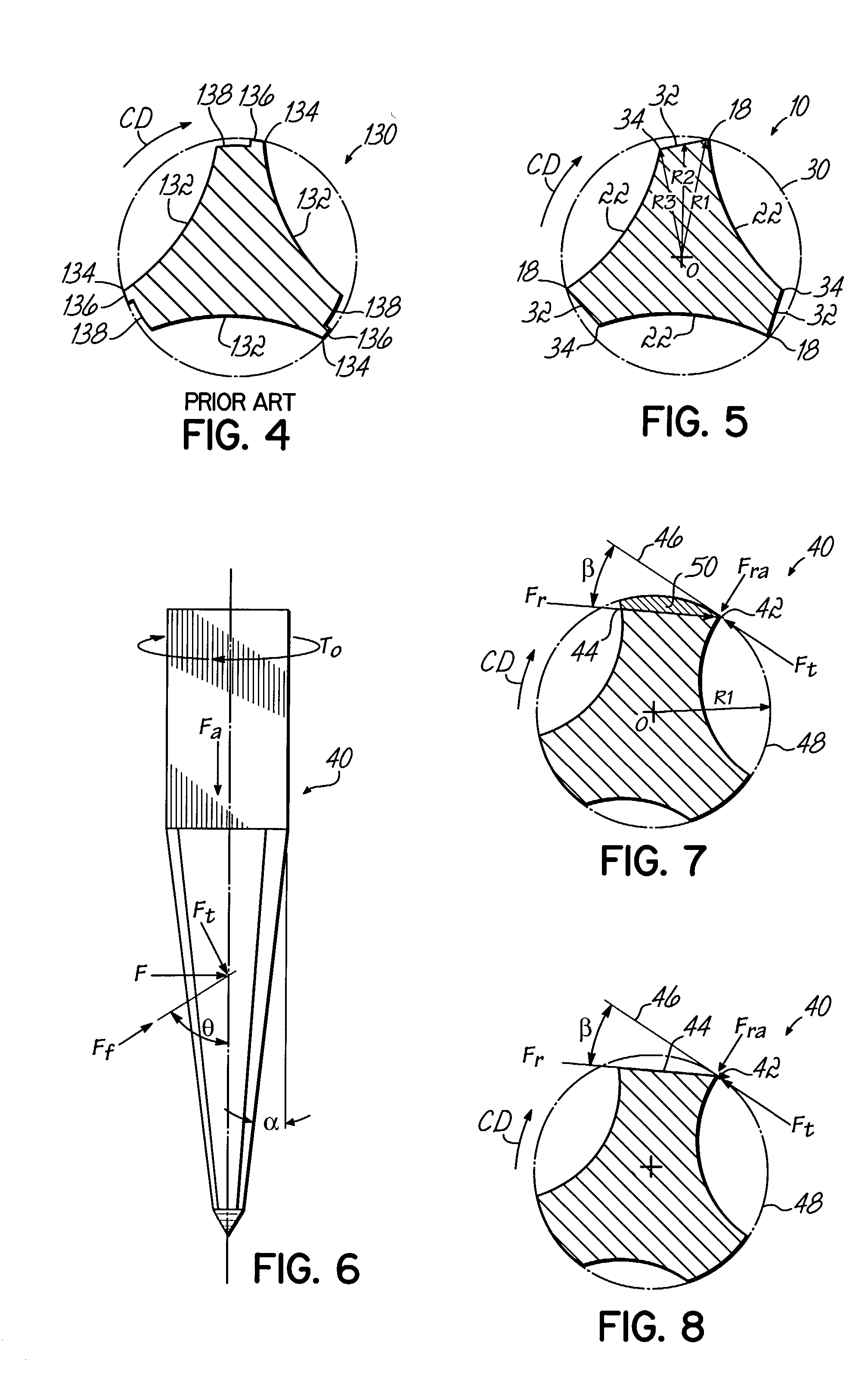
[0008]The present invention provides an endodontic instrument for use in shaping a root canal in which the cutting edges have been optimized for strength while minimizing the amount of friction generated within the canal. The instrument has an elongate shaft with a working length along a portion of the shaft. At least one non-landed flute is formed on the outer surface of the working length and defines a cutting edge at a radial distance from the axial center of the shaft. Behind the cutting edge, the outer surface of the shaft decreases in radial distance from the axial center of the shaft to form a peripheral flute surface that does not make contact with the interior surface of the root canal of the tooth. Advantageously, the peripheral flute surface provides strength to the cutting edge but does not create unwanted friction within the canal.
[0009]In an exemplary embodiment, the boundary of the peripheral flute surface behind the cutting edge is along a line of force defined by the resultant vector of the tangential and radial forces at the cutting edge. This configuration maximizes the effectiveness of the peripheral flute surface in strengthening the cutting edge because any material radially outward of the boundary does not contribute to strengthening the cutting edge.

Problems solved by technology

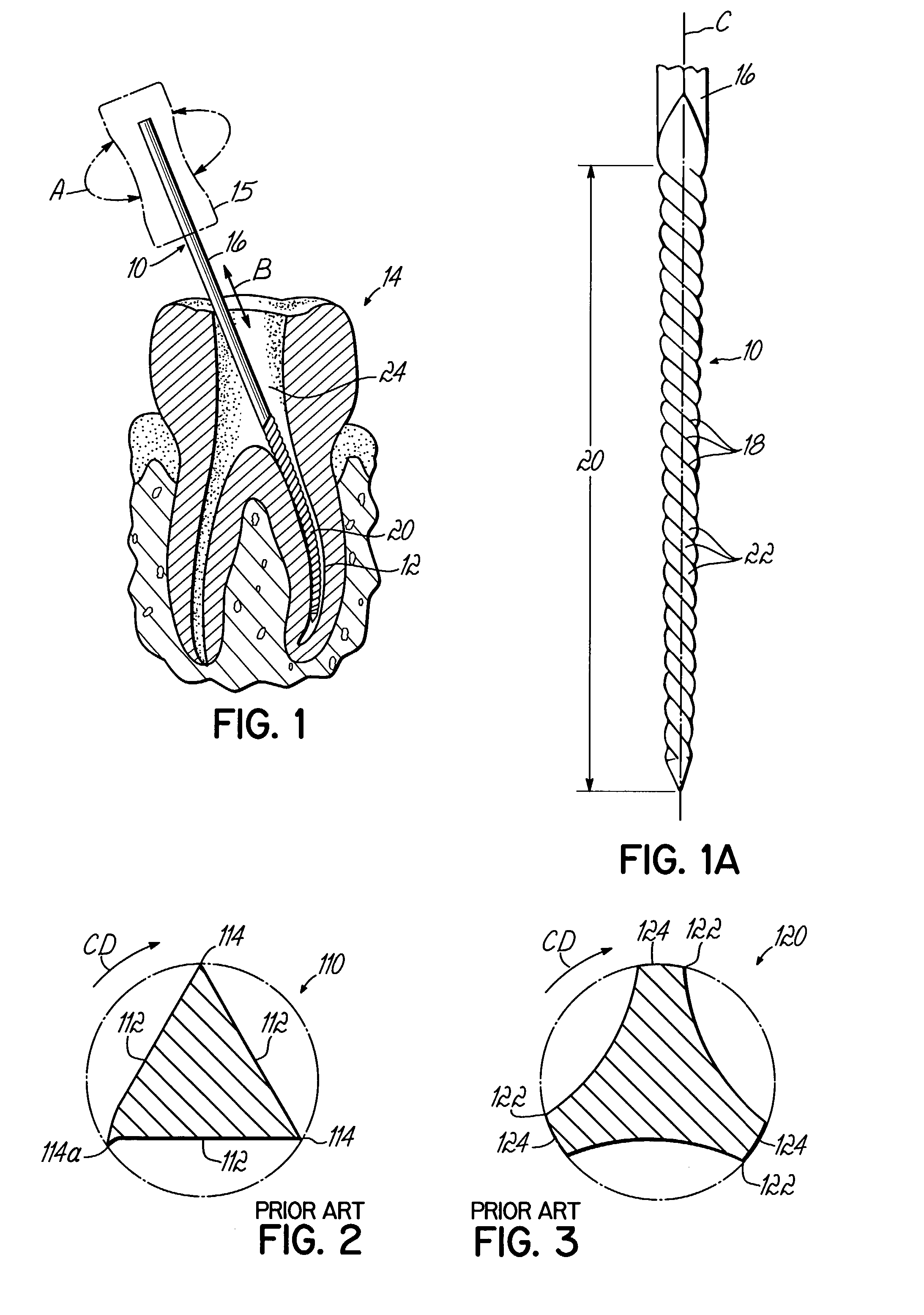
Such distortion of the cutting edge 114a severely lessens its effectiveness or makes the instrument 110 unusable.
While landed files exhibit increased strength at the cutting edge, they also significantly increase the friction between the file and the tooth.
This increased friction generates undesirable heat in the canal and increases the stress on the file, which can lead to failure and breakage of the instrument.
Indeed, one of the problems with traditional endodontic instruments used for extirpating and filing root canals is that the torsional limitations of the instrument are often exceeded, resulting in breakage of the instrument.
While these modified-land files provide improved strength, compared to non-landed files, they still generate undesired friction within the canal.

Method used


Image

  • Endodontic instrument
  • Endodontic instrument
  • Endodontic instrument

Examples


Embodiment Construction

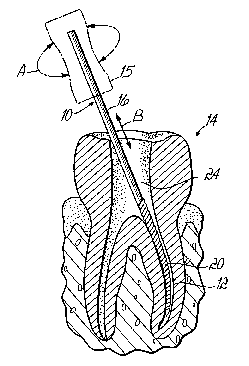
[0021]Referring to FIGS. 1–2, there is shown an exemplary endodontic instrument 10 of the present invention being used to shape a root canal 12 of a tooth 14. The endodontic instrument 10 includes a handle 15 for manual gripping by, for example, an endodontist and an elongate shaft 16 having cutting edges 18 for shaping the tooth 14. A portion of the shaft 16 comprises a working length 20 having helical flutes 22 which form the cutting edges 18 of the endodontic instrument 10. In use, the working length 20 of the instrument 10 is inserted into a root canal 12 of a tooth 14 through an upper interior portion 24 of the tooth 14 which has been initially opened using another instrument, such as a drill (not shown). Although files and reamers are typically manipulated manually, the instrument 10 of the present invention may be adapted for use with power operated equipment as well. In a conventional manner, the instrument 10 may be rotated in the direction of arrows A and / or reciprocated i...


PUM


Abstract

A non-landed endodontic instrument has flutes formed along a working length of the instrument shaft. The flutes define cutting edges for shaping a root canal of a tooth. The cutting edges lie at a major diameter of the shaft and peripheral flute surfaces behind the cutting edges extend along decreasing radial distances from the center of the shaft, in a direction opposite the cutting direction of the instrument.

Description

FIELD OF THE INVENTION[0001]This invention relates generally to the field of endodontics, and more particularly to instruments and methods for extirpating and enlarging a root canal.BACKGROUND OF THE INVENTION[0002]In the field of endodontics, one of the most important and delicate procedures is that of cleaning or extirpating a root canal to provide a properly dimensioned cavity while essentially maintaining the central axis of the canal. This step is important in order to enable complete filling of the canal without any voids and in a manner which prevents the entrapment of noxious tissue in the canal as the canal is being filled.[0003]In cleaning and enlarging the root canal, instruments called files, or reamers, are used. Commonly, both files and reamers have flutes which spiral along a portion of the instrument length and define cutting edges used to shape the root canals. The classification of an instrument as a file or a reamer depends upon the pitch of the flutes. A instrume...

Claims


Application Information

Patent Timeline
IPC IPC(8): A61C5/02A61C3/02
CPCA61C5/023A61C5/42
Inventor GARMAN, GARY T.
Owner ORMCO CORP
Learn More