Laser aim scoring system

a scoring system and laser technology, applied in direction controllers, training adaptation, instruments, etc., can solve the problems of limited target ranges, bore sighting of existing miles training systems, and extreme limitations in field training using live training rounds, while the preferred method is used

Inactive Publication Date: 2006-12-12
UNITED STATES OF AMERICA
View PDF11 Cites 3 Cited by
  • Summary
  • Abstract
  • Description
  • Claims
  • Application Information

AI Technical Summary

Benefits of technology

[0006]This invention enables real time simulation and feedback to the gunner by adding a “smart” hardware interface to the pop-up targets as found on military firing ranges. The target, typically a silhouette painted on plywood, is attached to a target pop-up device. A downrange programmable microprocessor with laser sensors and video camera is located near, and interfaced to the pop-up device. The sensors include both on-target and off-target detectors that sense laser radiation at the designator frequency. If mission requirements are met (i.e. proper designator code, laser time off-target, laser time on-target), the target pop-up device is commanded to drop the target, signifying a “hit”. The gunner, following proper engagement procedures, would instantly see the target drop at the proper round impact time. For added realism, the system can also command the Hoffman Target Kill Simulator to fire, ad

Problems solved by technology

For MILES training systems, however, target ranges are limited to 3 kilometers or less because of output power limitations with state-of-the-art laser diodes.
There are also problems with bore sighting of the existing MILES training systems.
Field training using live training rounds, while the preferred method, is

Method used


Image

  • Laser aim scoring system
  • Laser aim scoring system
  • Laser aim scoring system

Examples


Embodiment Construction

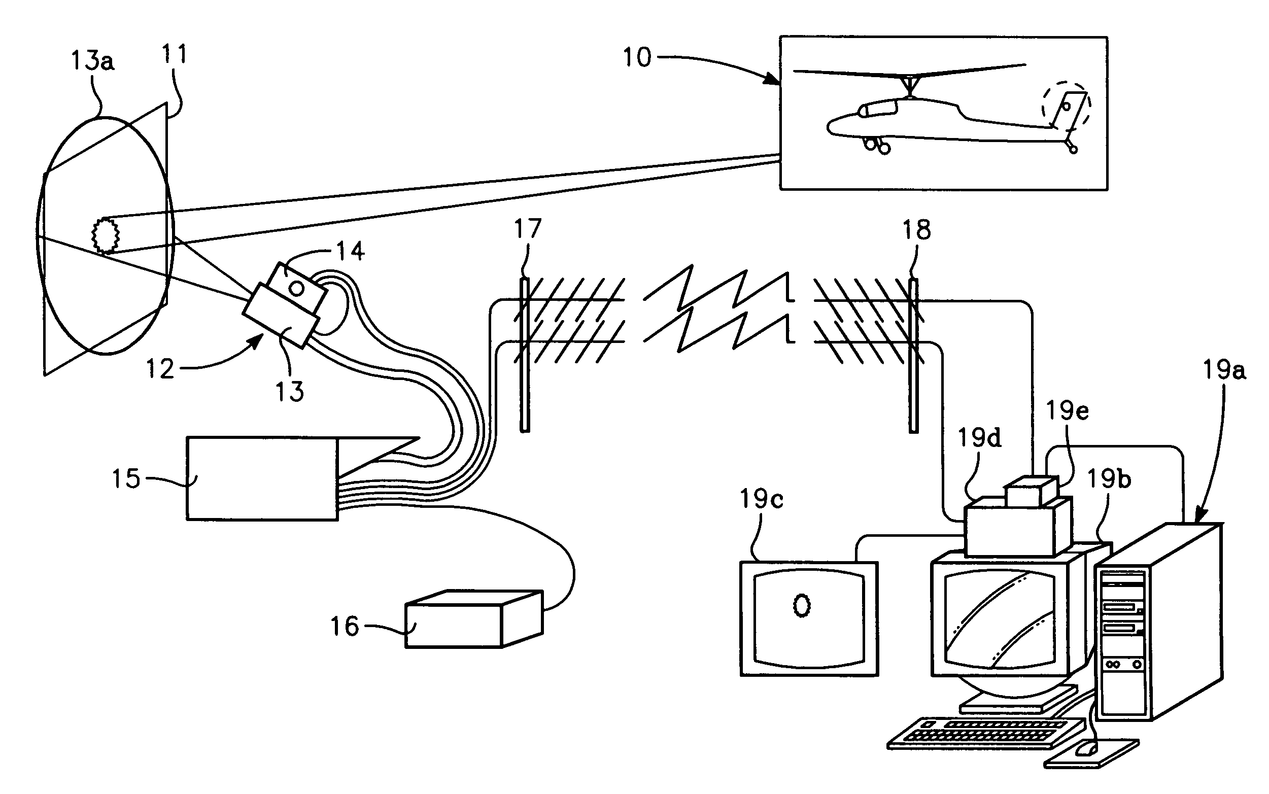
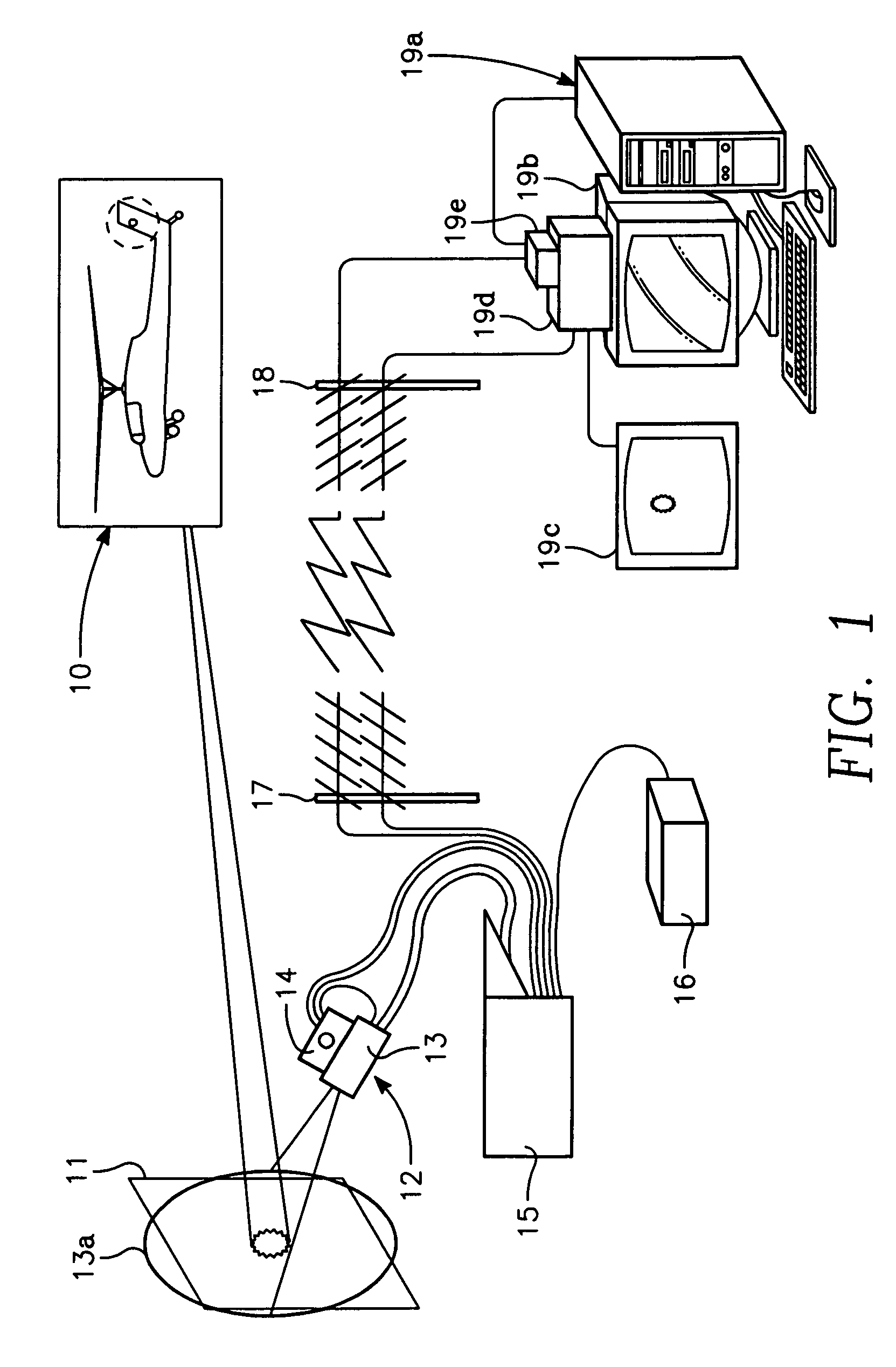
[0011]Referring to FIG. 1, there is shown a complete layout of the operating system of the present invention. The system operates on the principle that the success of the target engagement is directly related to the ability of the laser designator operator (the gunner) to properly aim the laser, near or on the target, at appropriate times during the flight of the missile. The drawing portrays a helicopter 10 or flying platform, which usually involves autonomous designations, i.e. the same platform both designates the target and launches the laser-guided munitions. The same concept can involve ground-based designators and ground based munitions. The system also supports buddy lasing, where either a ground gunner or air platform designates the target, or another platform launches the weapon. The target 11 is a flat pop-up board painted to provide the same contrast with the background, as would a real target. An active test monitor 12 is placed in front of the target far enough away an...


PUM


Abstract

A system, called the Laser Aim Scoring System, and method for automatically scoring gunner training sessions for simulated laser-guided missile, target engagements using the laser designator without the need for training or tactical rounds are disclosed. In the disclosed invention, a pop-up target and its surrounds are separately monitored for radiations at the laser designator frequency. “Hit” or “Miss” scoring is based on detection of the laser radiation at the laser designator frequency illuminating the appropriate region around or on the target at the appropriate time with respect to a simulated missile launch signal at the start of the training engagement, in accordance with the engagement profile programmed into the scoring computer prior to the start of training. The laser aim scoring system send a signal to lower the pop-up target in response to a “Hit” score, and if desired by the user, also sends a signal to initiate smoke and flash signals from a Hoffman Kill Simulator interfaced with the system. The disclosed invention also sends the appropriate signals at the end of the engagement to reset the target in the upright position so that it is ready for the next engagement. The disclosed invention includes subsystems for transmitting data, video imagery, and control signals between the portion of the system at the target location and the portion of the system at the control tower.

Description

BACKGROUND OF THE INVENTION[0001]1. Field of the Invention[0002]The invention relates to training equipment for use with laser-guided weapons including bombs, rockets and artillery shells.[0003]2. Description of Prior Art[0004]There is a large stockpile in the military inventory of laser-guided munitions. To insure that the services achieve maximum effect from such weapons requires a sophisticated training program. Available training facilities include ground based electronic training stations, field training using Multiple Integrated Laser Engagement System (MILES) type system, which employs a laser version of the old game called “Tag”, and field training using “live” training rounds. The use of ground based electronic stations, while useful for introductory training, is not the preferred method. Field training is a far more effective method. For MILES training systems, however, target ranges are limited to 3 kilometers or less because of output power limitations with state-of-the-...

Claims


Application Information

Patent Timeline
IPC IPC(8): F41A33/00F41G3/26G09B19/00
CPCF41A33/00F41G7/006F41J5/02
Inventor HABERSAT, JAMES D.REDMAN, BRIAN C.LEI, JONATHAN S.NETTLETON, JOHN E.QUARLES, MICHAEL M.
Owner UNITED STATES OF AMERICA
Why Eureka
Try Eureka