Power generating and propelling system of vessel

a technology of power generation and propelling system, which is applied in the direction of vessel auxiliary drive, motor-driven power plants, vessel parts, etc., can solve the problems of exhaust gas, vibration and noise, and achieve the effect of efficient use of wasted hea

Inactive Publication Date: 2006-12-12
YANMAR CO LTD
View PDF15 Cites 38 Cited by
  • Summary
  • Abstract
  • Description
  • Claims
  • Application Information

AI Technical Summary

Benefits of technology

[0024]Therefore, by using the cooling water after cooling the electric motor for inboard warm water supply etc., wasted heat can be used efficiently while ensuring facilitation of assembly and maintenance of the electric motor.

Problems solved by technology

Consequently, exhaust gas, vibration and noise always occur while propelling.

Method used


Image

  • Power generating and propelling system of vessel
  • Power generating and propelling system of vessel
  • Power generating and propelling system of vessel

Examples


Embodiment Construction

[0035]The present invention will be detailed in accordance with accompanying drawings.

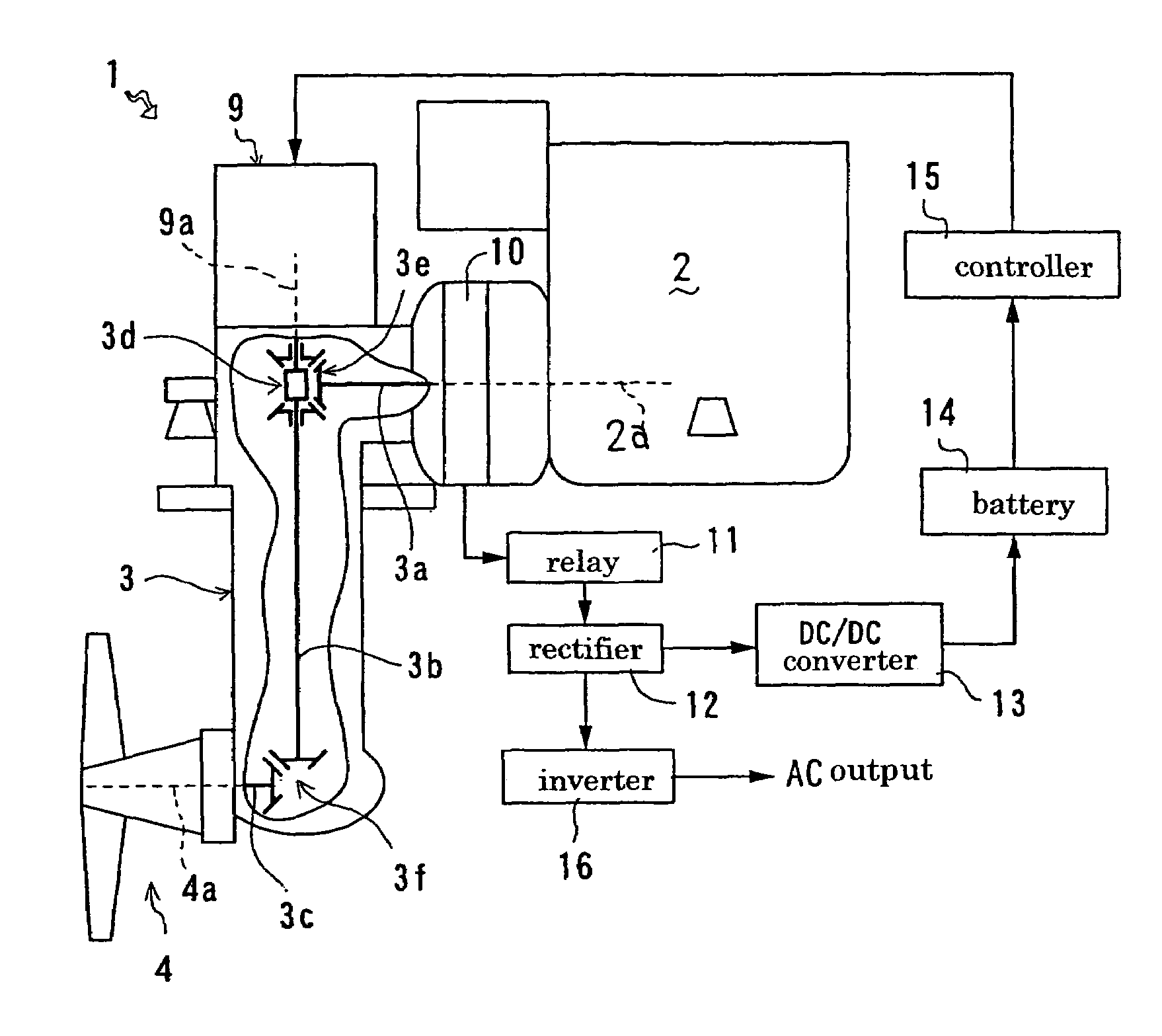
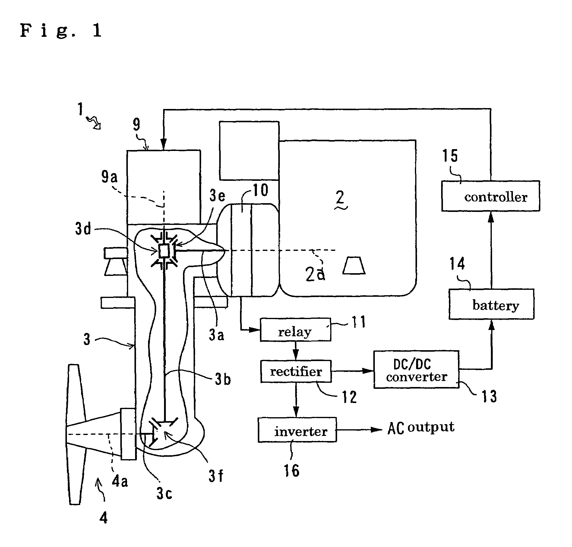
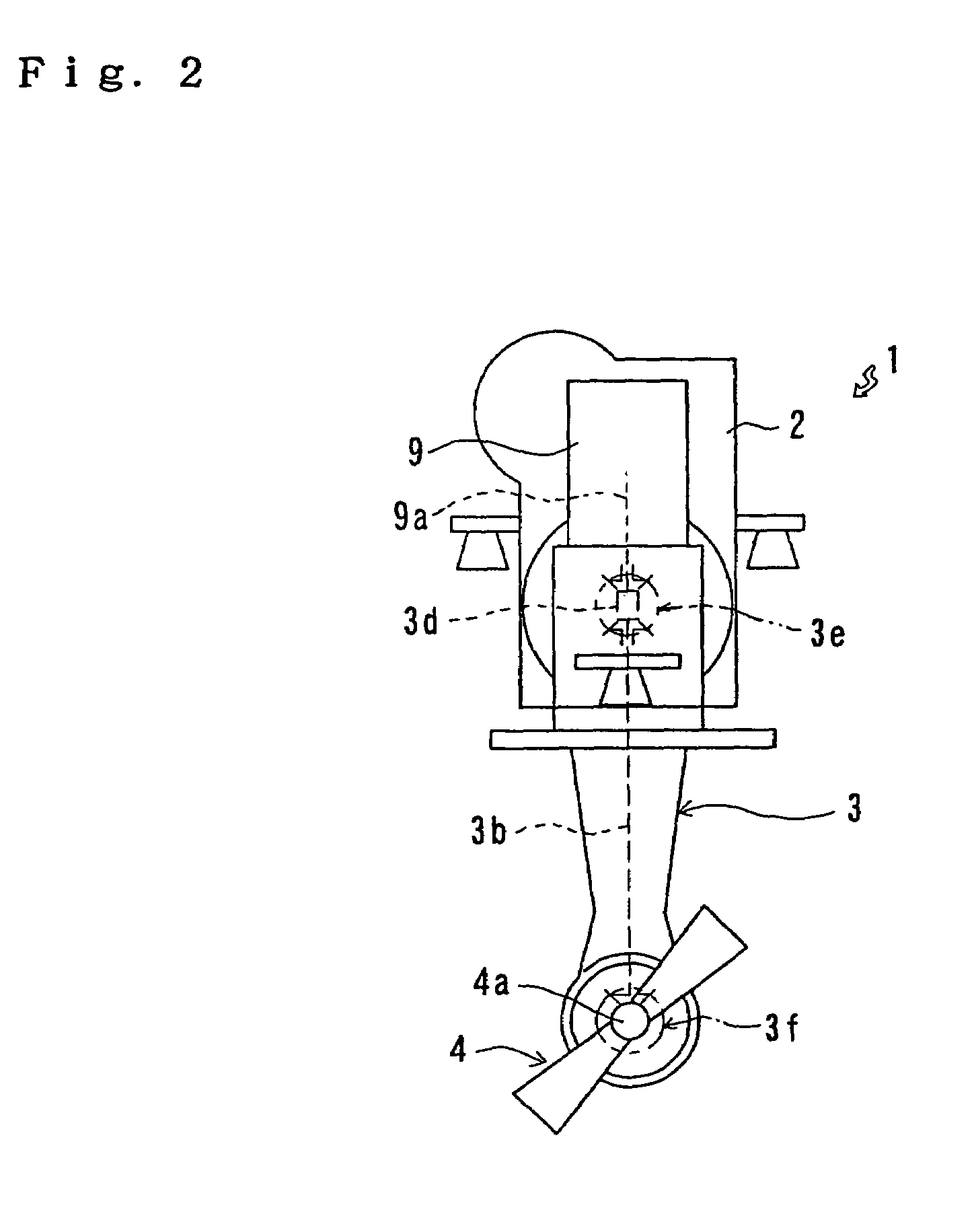
[0036]A propelling machine employing a power generation and propelling system of a vessel according to the present invention will be described. A propelling machine 1 shown in FIGS. 1 and 2 has an internal combustion engine 2 and a power transmission device 3, which is constructed as a sail drive system and connected with a propeller 4. Driving force from the internal combustion-engine 2 is transferred to the propeller 4 while being decelerated by the power transmission device 3, thereby rotating the propeller 4.

[0037]Additionally, with regard to the propelling machine 1, an electric power generating equipment 10 having a generator or characteristics thereof is interposed between the internal combustion engine 2 and the power transmission device 3. The power generating equipment 10 is driven by the internal combustion engine 2 so as to generate electric power, which is used for driving a later-disc...


PUM


Abstract

An electric power generating equipment (10) is provided between an internal combustion engine (2) and a power transmission device (3), and an electric motor (9) is disposed at an area of the power transmission device. An output shaft (9a) of the electric motor (9) is disposed coaxially to any of rotary shafts of the power transmission device (3).

Description

TECHNICAL FIELD OF THE INVENTION[0001]The present invention relates to the construction of a propelling machine of a vessel, which is provided with an electric motor in addition to an engine as a power source for propelling the vessel, so that the vessel can be propelled by the engine with assist of the electric motor or by only the electric motor.BACKGROUND ART[0002]Conventionally, a propelling machine of a vessel comprises an internal combustion engine, a power transmission device, and others. The power transmission device decelerates driving force of the engine, and drives a propeller connected to the power transmission device. When the vessel is propelled, the engine is always driven. Even if the vessel sails at low speed, the propeller is driven by the engine. Consequently, exhaust gas, vibration and noise always occur while propelling.[0003]Moreover, inboard electrical equipments are supplied with electric power stored in a battery. A generator for charging electric power to t...

Claims


Application Information

Patent Timeline
Patent Type & Authority Patents(United States)
IPC IPC(8): B63H21/20B63H21/17B63H21/21B63H20/00B63H20/14B63H21/12B63H21/14B63H23/14B63H23/24B63J3/02F02B73/00
CPCB63H20/00B63H20/28B63H21/20B63J3/02F02B73/00B63H20/14B63H2021/202B63H2021/205Y02T70/5236B63H23/14Y02T10/70
Inventor MORI, HISANORINAKAGAKI, MITSUHIROTODA, TAKAYUKIHITACHI, JUNICHI
Owner YANMAR CO LTD
Why Eureka
Try Eureka