
Wastewater treatment system with membrane separators and provision for storm flow conditions

a technology of storm flow and sewage treatment system, which is applied in the direction of biological water/sewage treatment, multi-stage water/sewage treatment, sustainable biological treatment, etc., can solve the problems of limited peak flow conditions of mbrs, high cost and excess capacity of normal flow

Active Publication Date: 2006-12-12
OVIVO INC
View PDF11 Cites 83 Cited by
  • Summary
  • Abstract
  • Description
  • Claims
  • Application Information

AI Technical Summary

Benefits of technology

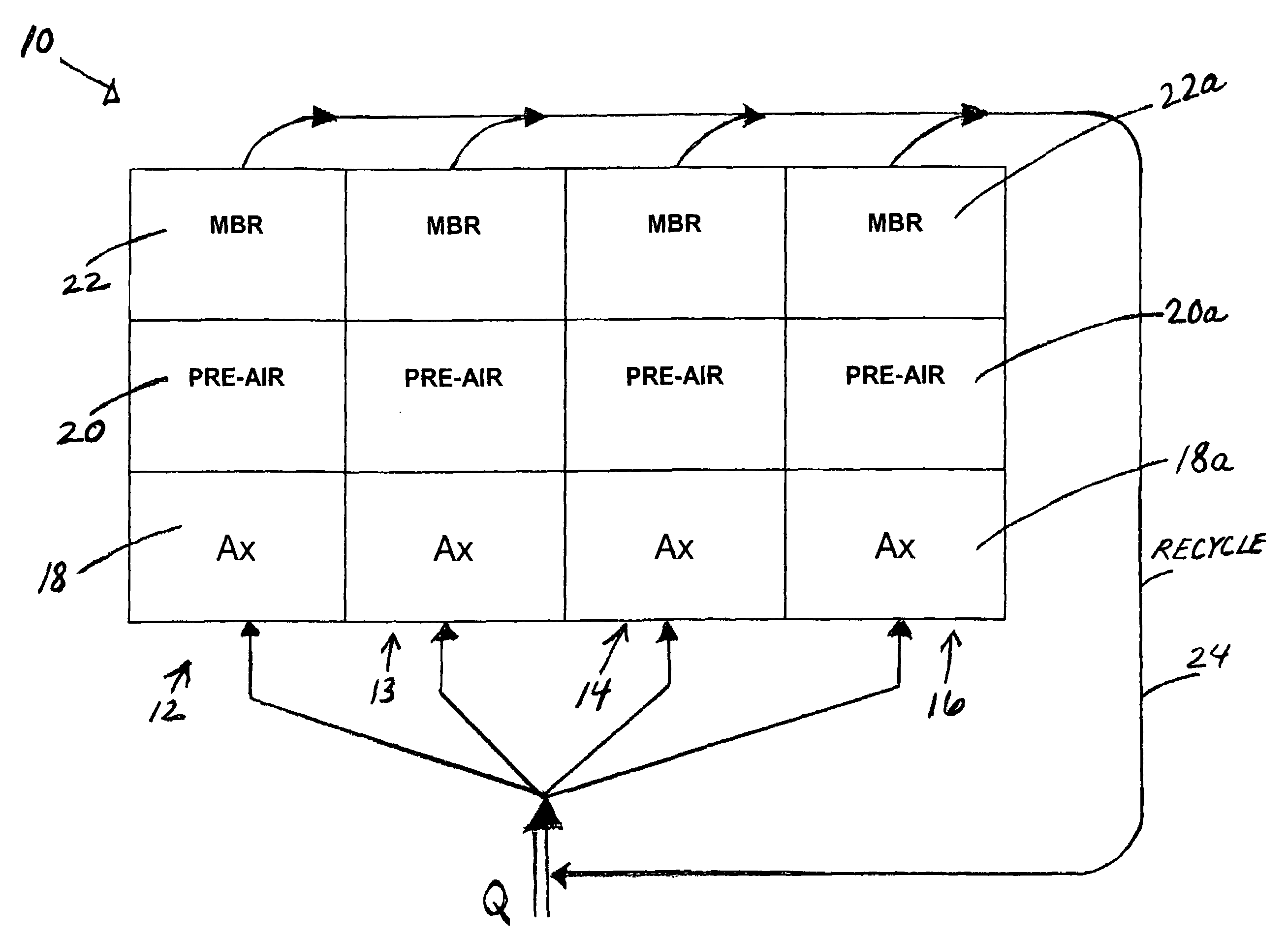
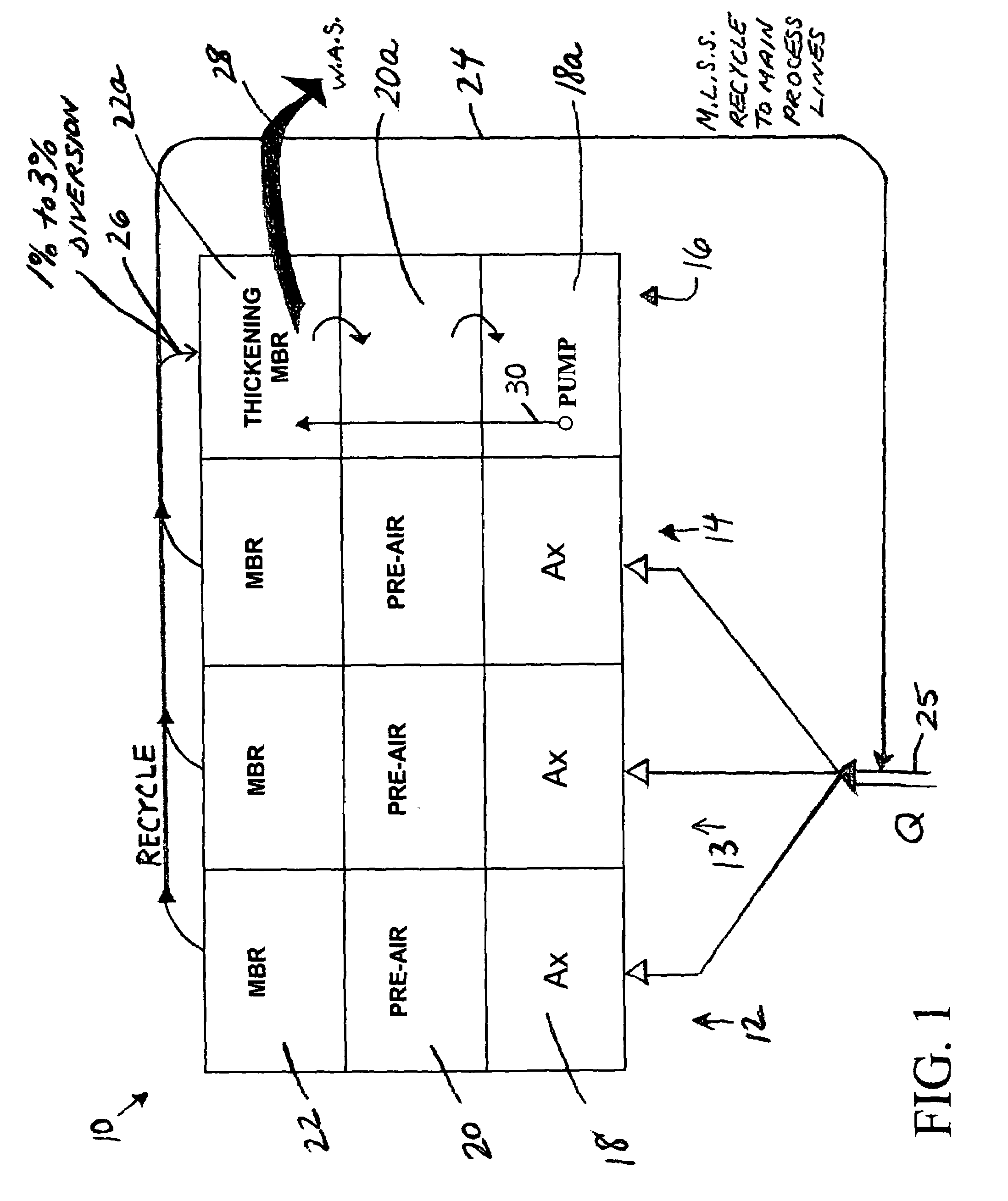
[0008]Another advantage of the described configuration is that with the thickened sludge in the special process line, thickened and digested during normal operation, there is additional biomass available to handle the peak flow. In other words, additional biomass is available if needed for a sudden onslaught of heavy flow, or if an event occurs bringing a toxic situation into the main basins. The sludge in the special line(s) can be used to reseed the on-line basins, redistributing this sludge to all basins. An additional advantage is that where the system has multiple lines and only two or three are in use out of e.g., six, then when additional lines are to be started up they can be seeded with the digestion sludge.

Problems solved by technology

MBRs, however, are limited in terms of peak flow conditions, due to their inability to handle high peak flow conditions, normally no more than twice design flow.
The MBRs in such a system were required to be designed to handle peak flow or storm conditions which could be up to three times normal flow, requiring much excess capacity and cost as regards normal flow.

Method used


Image

  • Wastewater treatment system with membrane separators and provision for storm flow conditions
  • Wastewater treatment system with membrane separators and provision for storm flow conditions
  • Wastewater treatment system with membrane separators and provision for storm flow conditions

Examples


example

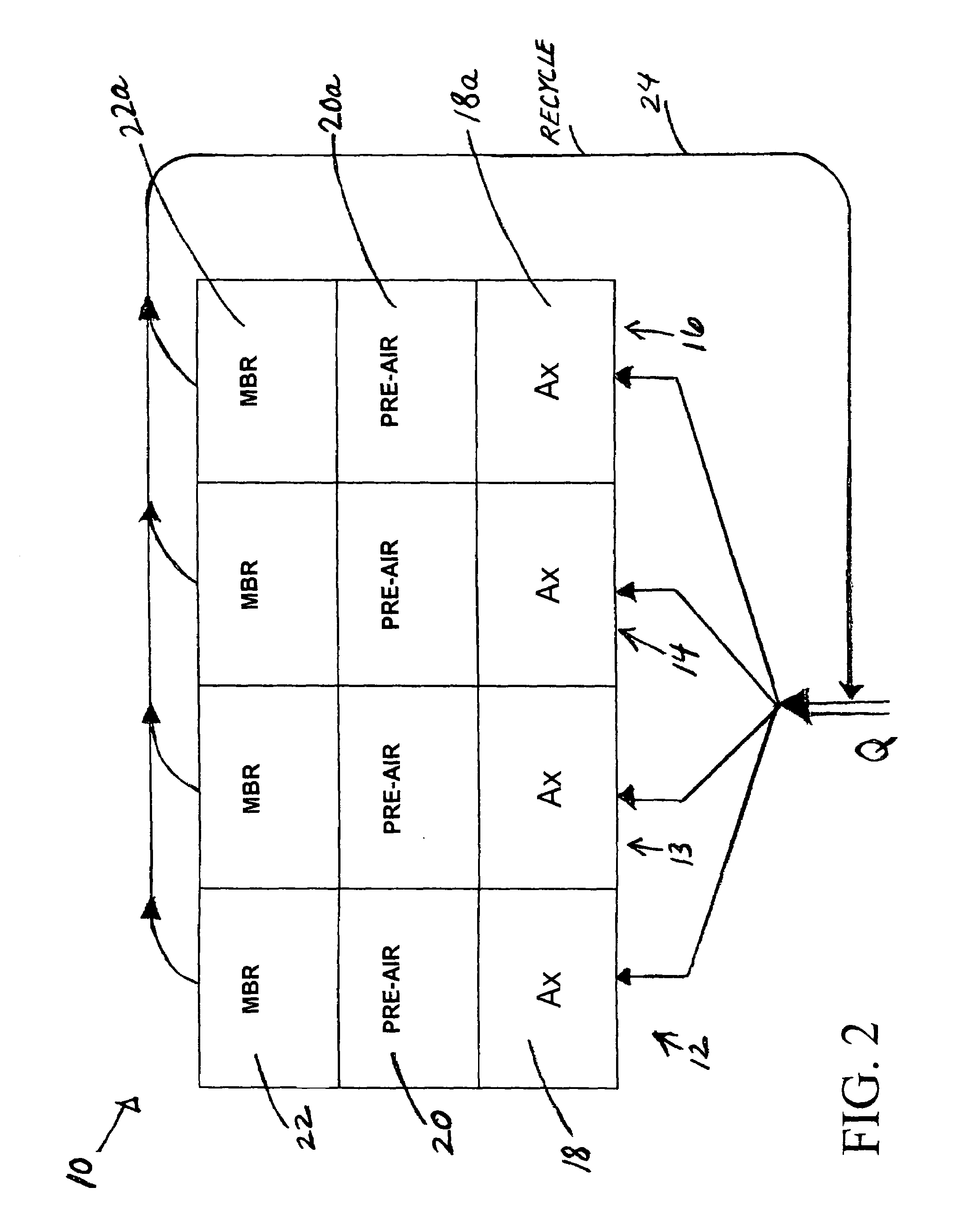
Three normal process lines, one special process line, 1 mgd design flow, 3Q peak flow

Normal Operation

2 or 3 MBR's operational

1 MBR Thickening to 30,000 mg / l (3% solids)

Feed at 10,000 mg / l from the recycle stream (1% solids)

Peak Flow Operation

All four MBR's operate in same manner, in parallel M.L.S.S. in thickening MBR included in recycle providing additional biomass redistributed over all 4 basins

3 at 10,000; 1 at 30,000

4 at 15,000 mg / l, as redistributed

1 mgd example with 3Q peaking factor (1.5 mgd of membranes since membranes can handle up to double design flow)

4 basins MBR

Each Basin Designed to Handle

3 mgd÷(2×4)=0.375 mgd

Total membranes=12,000 (based on 125 gpd design flow / membrane)

Use 8×EK400* / basin=12,800 cartridges *EK400: Kubota model designation

MBR basin Volume 5390 ft3×7.48 ft3 / gal×4 basins=161,269 gallons (based on tank volume recommendation for MBR area?)

Pre-Air=100,000 gallons (based on B.O.D.)

Anoxic volume 80,000 gallons (based on organic load and effluent requirements)=...


PUM

PropertyMeasurementUnit
concentrationaaaaaaaaaa
Volumeaaaaaaaaaa
volumeaaaaaaaaaa

Abstract

In a wastewater treatment system and process utilizing membrane bioreactors (MBRs), multiple, parallel series of tanks or stages each include, an MBR stage. Under conditions of normal flow volume into the system, influent passes through several parallel series of stages or process lines, which might be, for example, an anoxic stage, an aeration stage and an MBR stage. From the MBR stages a portion of M.L.S.S. is cycled through one or more thickening MBRs of similar process lines, for further thickening and further processing and digesting of the sludge, while a majority portion of the M.L.S.S. is recycled back into the main process lines. During peak flow conditions, such as storm conditions in a combined storm water / wastewater system, all of the series of stages with their thickening MBRs are operated in parallel to accept the peak flow, which is more than twice normal flow. M.L.S.S. is recycled from all MBR stages to the upstream end of each of all the parallel process lines, mixing with influent wastewater, and the last one or several process lines no longer act to digest the sludge. Another advantage is that with the thickened sludge in the last process line of basins, which ordinally act to digest the sludge, there is always sufficient biomass in the system to handle peak flow, the biomass being available if needed for a sudden heavy flow or an event that might bring a toxic condition into the main basins.

Description

BACKGROUND OF THE INVENTION[0001]This invention is concerned with wastewater treatment, and particularly a sewage treatment plant including membrane separators, in a system that can handle up to three times or more normal flow during peak flow conditions, such as storm conditions in a combined sewer system. The invention enables the use of membrane separators for both a storm event and for sludge stabilization during normal flow, with minimum operator intervention.[0002]Membrane separators, sometimes called membrane bioreactors or MBRs, have come into increasing use in recent years, particularly in small to medium sized sewage treatment plants, as an efficient means of removing water and thickening sludge in a way that conserves space and capital cost. MBRs, however, are limited in terms of peak flow conditions, due to their inability to handle high peak flow conditions, normally no more than twice design flow. To overcome this limitation, either additional membranes must be utilize...

Claims


Application Information

Patent Timeline
Patent Type & Authority Patents(United States)
IPC IPC(8): C02F3/30
CPCC02F3/1268C02F3/302Y02W10/10
Inventor PORTEOUS, JAMES
Owner OVIVO INC
Learn More