Pneumatic paintball marker

a paintball marker and pneumatic technology, applied in the field of paintball markers, can solve the problems of difficulty in cleaning, decreased flight accuracy, and less efficient spool or dump valves, and achieve the effects of reducing the weight, and reducing the size of the marker

Inactive Publication Date: 2006-12-19
RICE JACK V
View PDF15 Cites 38 Cited by
  • Summary
  • Abstract
  • Description
  • Claims
  • Application Information

AI Technical Summary

Benefits of technology

[0034]The present invention is distinguished over the known prior art in a multiplicity of ways. For one thing, an embodiment of the invention provides a pneumatic paintball marker comprised offset or nonparallel sealing such that a desirable reduction in size and weight and is accomplished by the unique use of a cam and a pivoting door arrangement to affect upper firing chamber sealing and the use of a removable back plug which seals a rear of the firing chamber whi

Problems solved by technology

Spool or dump valves being less efficient but acceptable.
An increase in turbulence has been acknowledged to cause a decrease in flight accuracy.
One, its difficulty in cleaning in the event of a broken paintball in the marker housing.
Therefore dump valve markers can only be cleaned from the front.
Two, its lower gas efficiency.
Transitioning paintball with air used to propel paintball results in increased paintball breakage, increased turbulence and decreased air efficiency.
However with the use of a door sealing over the paintballs, the entire width of the door impacts paintball and occupies the space previously taken by the paintball.
These markers provide good sealing and loading but, have inherent liabilities a slower speed of operation than is possible in the art and a decrease in air efficiency.
Limitation of these markers include: Paintball not being transitioned into barrel, lower speed of operation and less gas efficient.
Inherent limitations including: air used to propel paintball was used to transition paintball, lower speed of operation, loss of air efficiency and most notably the impact of door on the paintball next to be loaded.
The marker manufactured by Insight Component Engineering and sold under the name EPIC has engineering ch

Method used


Image

  • Pneumatic paintball marker
  • Pneumatic paintball marker
  • Pneumatic paintball marker

Examples


Embodiment Construction

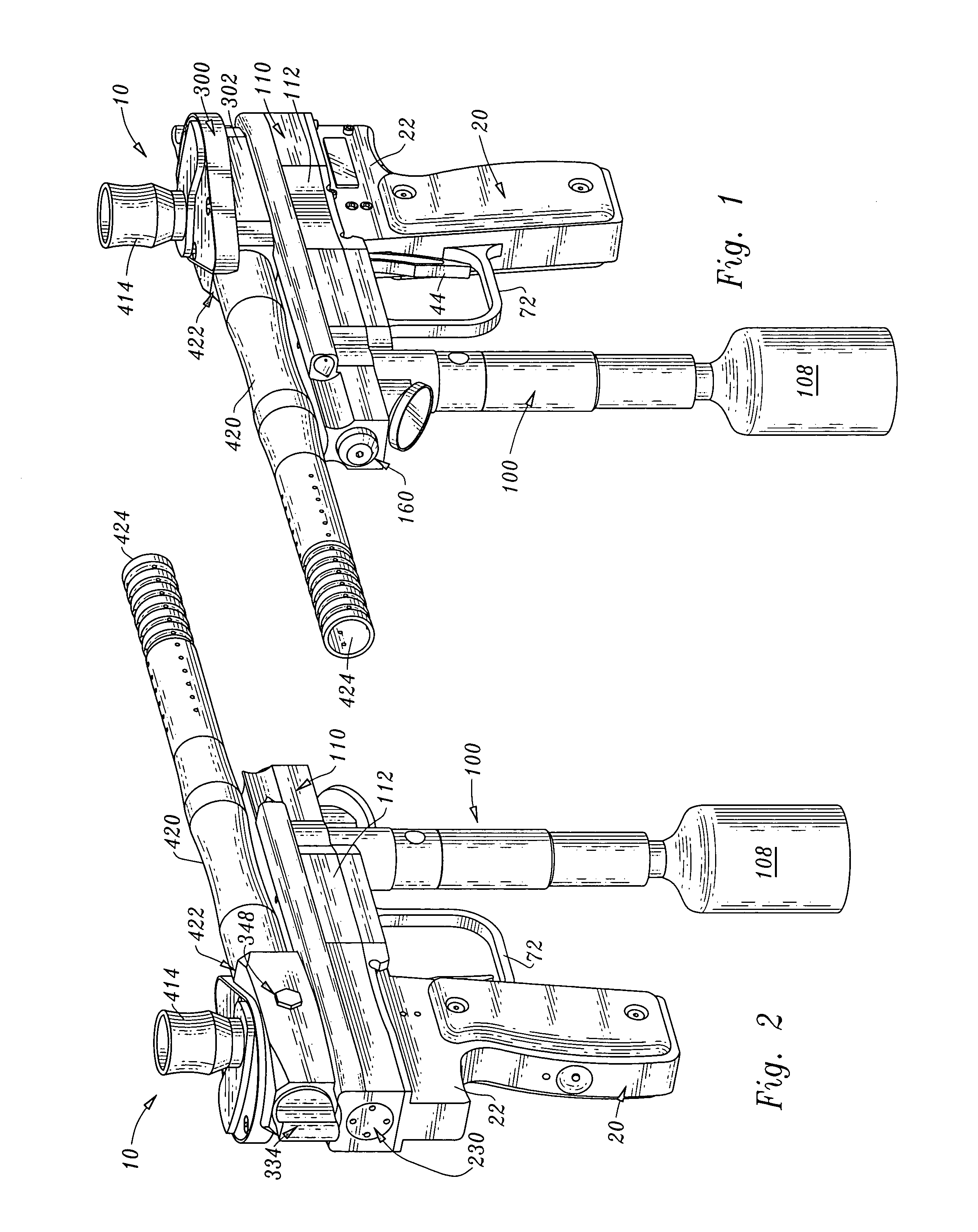
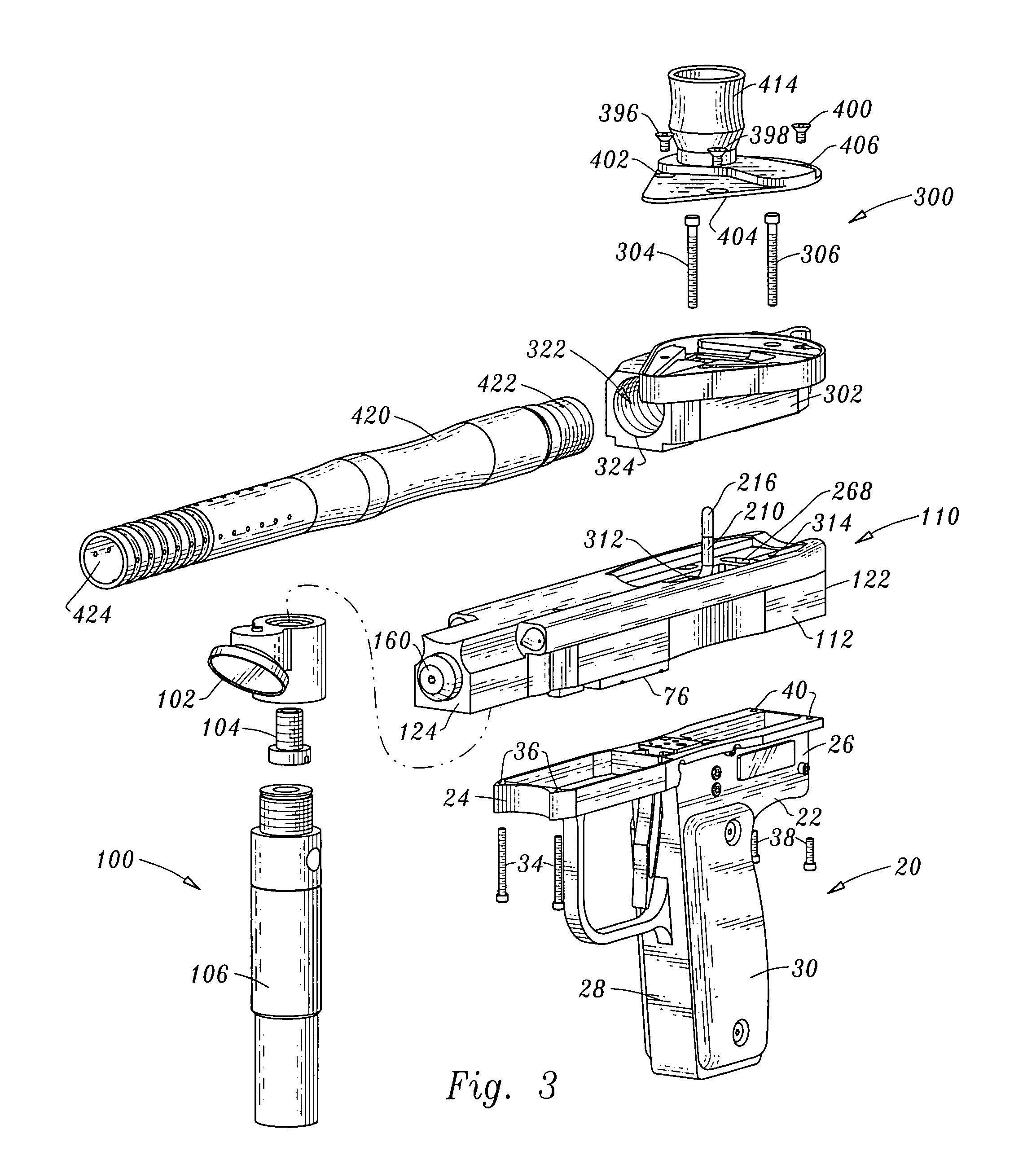
[0074]Considering the drawings, wherein like reference numerals denote like parts throughout the various drawing figures, reference numeral 10 is directed to a pneumatic paintball marker.

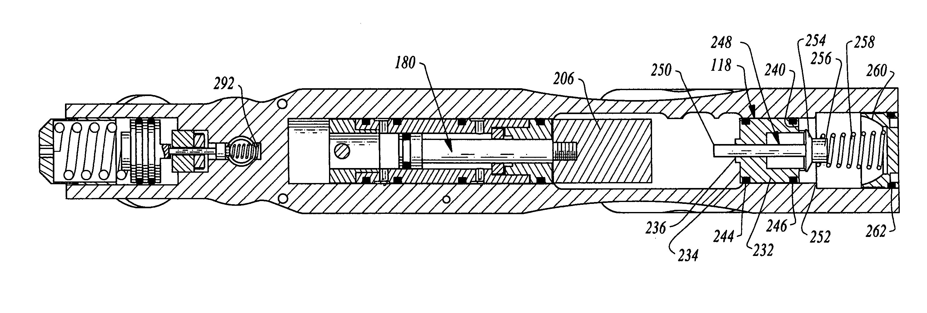
[0075]In its essence, and referring to the drawings, one embodiment of the invention provides a paintball marker 10 comprised of a hollow open ended firing chamber 322 having a barrel 420 coupled to one end 324 and a removable back plug 334 coupled to an opposing end 326, a door 360 surmounting a paintball loading hole 328 disposed between the back plug 334 and the barrel 420; a cam 370 coupled to the door 360; an actuator 180 coupled to the door cam 370; a pin valve 230 interposed in a first gas path between a source of compressed gas 108 and a passage 332 leading to the firing chamber 322, and a trigger 44 operatively coupled to a second gas path between the source of compressed gas 108 and the actuator 180 for opening the second gas path for actuating the actuator 180 such that the door cam 370 t...


PUM


Abstract

Paintball marker including a firing chamber having a barrel coupled to one end and a removable back plug coupled to an opposing end, a door surmounting a chamber loading hole disposed between back plug and barrel; a cam coupled to door; an actuator coupled to door cam; a pin valve interposed in a first gas path between a gas source and a passage leading to the chamber, and a trigger coupled to a second gas path between the gas source and actuator for opening the second gas path for actuating the actuator such that the door cam transforms motion of the actuator into pivoting motion of the door from an open position such that a paintball is loaded into the chamber to a closed position and then continuing to actuate the actuator to coact with the pin valve for opening the first gas path for firing the paintball.

Description

CROSS-REFERENCE TO RELATED APPLICATIONS[0001]This application claims benefit under Title 35, United States Code § 119(e) of U.S. Provisional Application No. 60 / 485,805 filed on Jul. 9, 2003.[0002]This application incorporates herein by reference the entire contents of pending U.S. patent application Ser. No. 10 / 033,161 filed on Oct. 26, 2001 and for which a notice of allowance was provided on Jun. 29, 2004.FIELD OF THE INVENTION[0003]This invention relates generally to paintball markers for firing paintballs with sufficient velocity to explode the paintballs against a target and, in particular, to pneumatic paintball markers which are capable of rapidly firing a large number of paintball rounds.BACKGROUND OF THE INVENTION[0004]Paintball markers are popular for firing a spherical ball loaded with a marking dye designed to rupture and mark a target on contact. Typical markers have an appearance similar to a handgun or small rifle but are typically fired by compressed air rather than a...

Claims


Application Information

Patent Timeline
IPC IPC(8): F41B11/32
CPCF41B11/62F41B11/71F41B11/722F41B11/723
Inventor RICE, JACK V.
Owner RICE JACK V
Why Eureka
Try Eureka