ROV retrievable sea floor pump

a technology of retrievable pumps and sea floor, which is applied in the direction of liquid fuel engines, wellbore/well accessories, sealing/packing, etc., can solve the problems of large potential reservoirs that cannot be used for long-term storage, large potential reservoirs are non-economical, and the production tubing is much more expensive than the production tubing on the offshore well. , to achieve the effect of avoiding the pollution of well fluid

Active Publication Date: 2006-12-19
BAKER HUGHES INC
View PDF14 Cites 55 Cited by
  • Summary
  • Abstract
  • Description
  • Claims
  • Application Information

AI Technical Summary

Benefits of technology

[0006]In this invention, a mudline or seafloor pump system is employed that allows retrieval of the pump without the use of a riser. A primary housing is located subsea at seafloor. The primary housing communicates with an intake conduit for receiving well fluid from an adjacent well or wells. A capsule lands in the primary housing and has an inlet that sealingly engages the receptacle of the primary housing for receiving well fluid flowing through the primary housing. A submersible pump assembly is located inside the capsule. The pump assembly has an intake that receives well fluid from the capsule and discharges the well fluid from the capsule. The capsule is retrievable from the primary housing through the open sea. Since only its interior is exposed to well fluid, the capsule avoids pollution of well fluid with the sea.

Problems solved by technology

Pulling production tubing on an offshore well is much more expensive than a land-based or surface wellhead.
The cost, coupled with lost production, will in some cases make large potential reservoirs non-economical.
A number of problems are associated with the task, including periodically replacing the pump from the seafloor without the need for an expensive workover or drilling rig.
If a riser must be employed to remove and replace a seafloor or mudline pump, a workover rig must still be employed at a great expense.

Method used


Image

  • ROV retrievable sea floor pump
  • ROV retrievable sea floor pump
  • ROV retrievable sea floor pump

Examples


Embodiment Construction

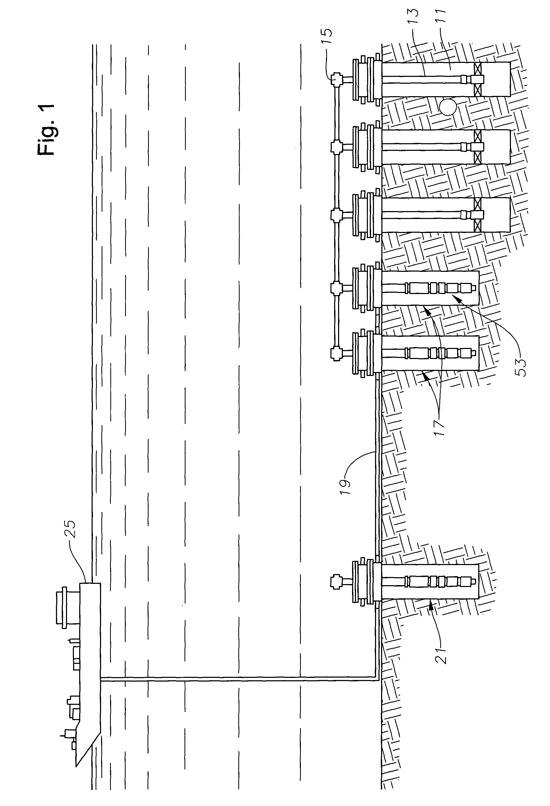
[0012]Referring to FIG. 1, a plurality of subsea wells 11 are schematically shown. The system of FIG. 1 is particularly suitable for medium to deep water subsea wells, wherein the water depth comprises at least 60% of the distance from the earth reservoir or perforations in the well to sea level. Subsea wells 11 may be a variety of types. Each shows a production tubing 13 suspended within a casing that is perforated for the flow of well fluid. Wells 11 are shown to be a type having a flowing pressure sufficient to flow well fluid from the perforations to the surface of each well 11 at the seafloor. A plurality of jumper flowlines 15 connect the various wells 11. Wells 11 are routed to a pumping assembly 17 directly or through a manifold (not shown).

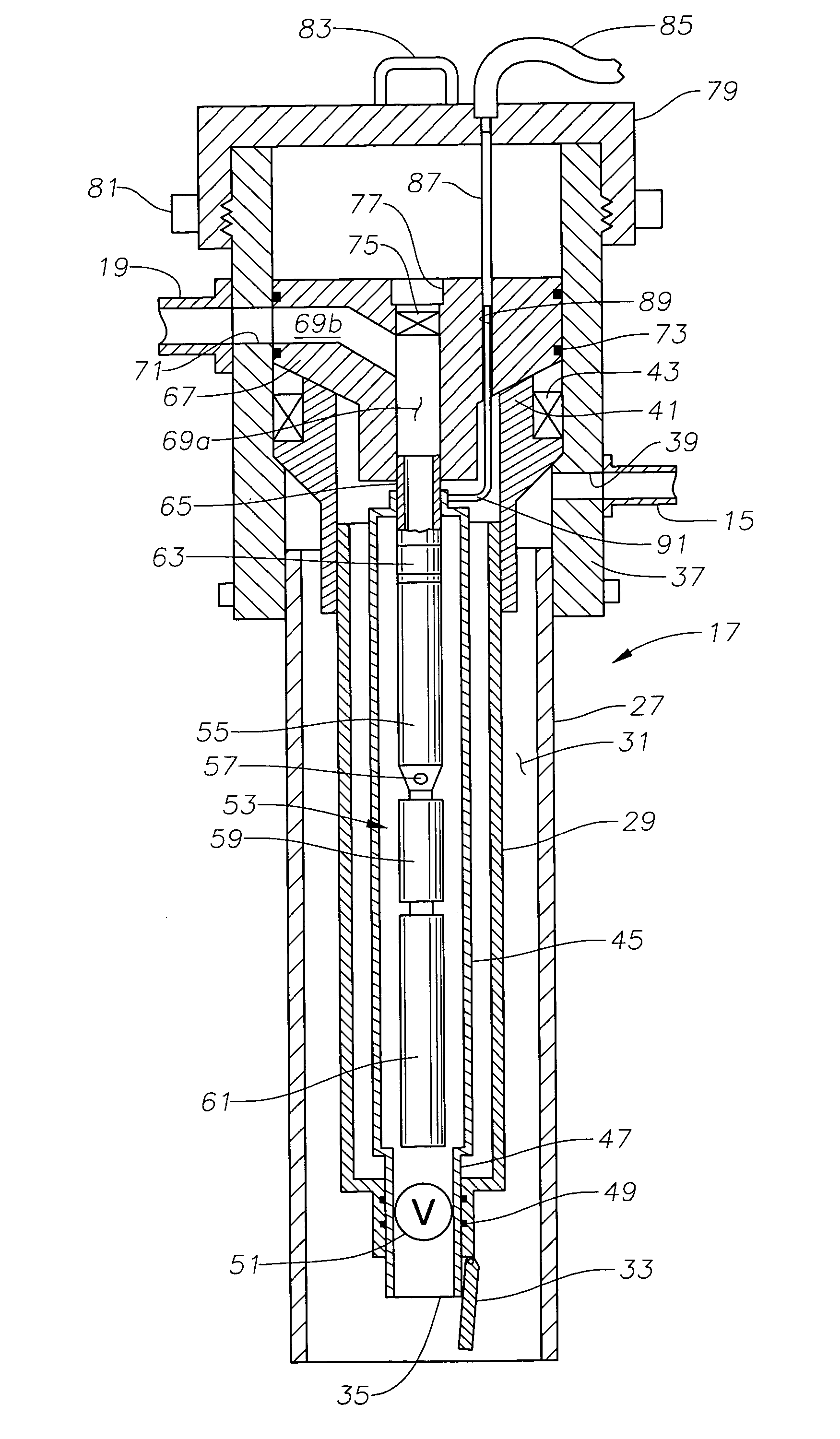
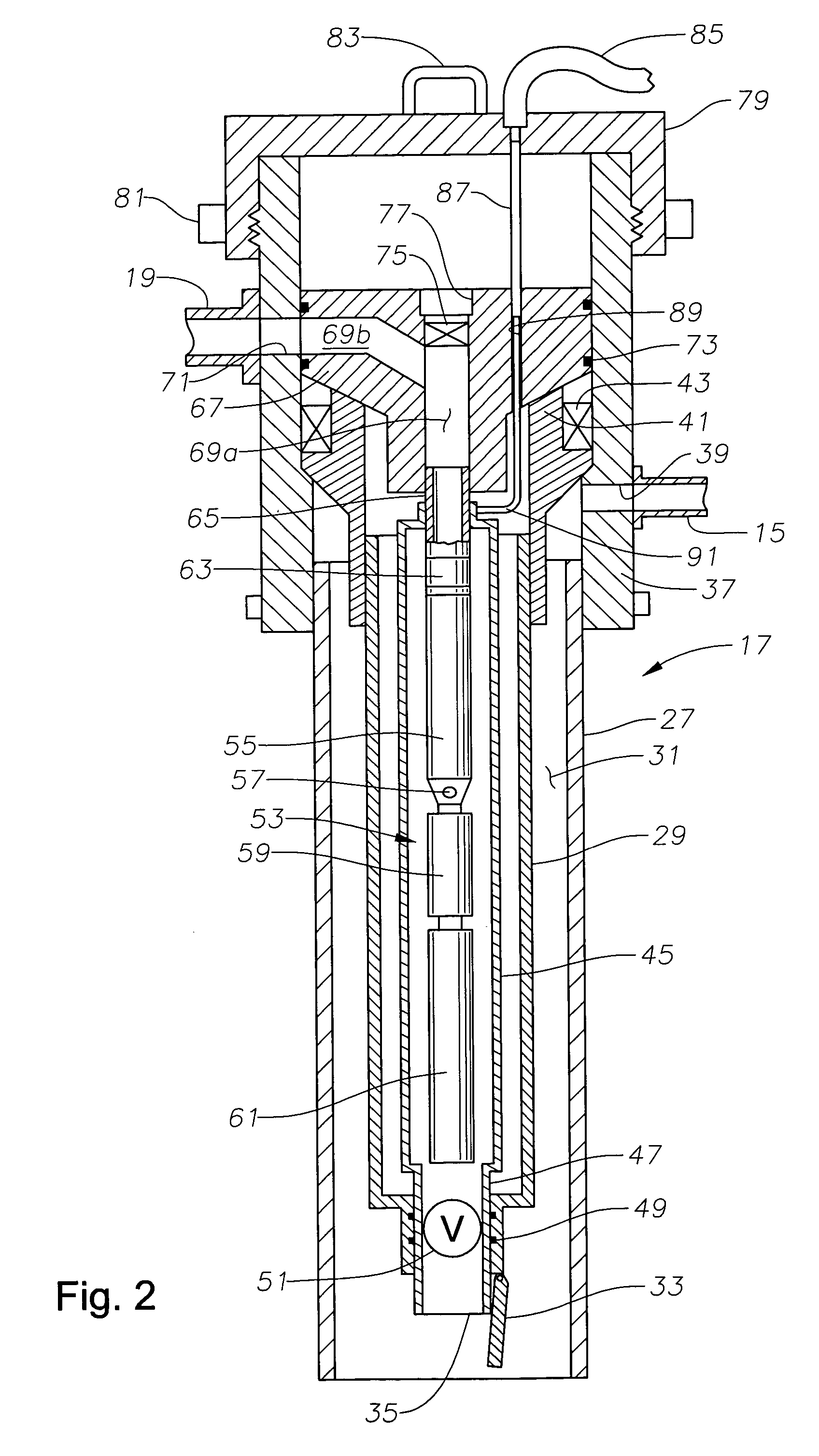
[0013]Pumping assembly 17 is also located at the mudline on the seafloor. In this example, pumping assembly 17 comprises two separate redundant pumping assemblies that are connected in parallel so that one can be removed for replacement o...


PUM


Abstract

A subsea pumping assembly locates on a seafloor for pumping well fluid from subsea wells to the level. The pumping assembly has a tubular outer housing that is at least partially embedded in the seafloor. A tubular primary housing locates in the outer housing and has a lower end with a receptacle. An annular space surrounds the primary housing within the outer housing for delivering fluid to a receptacle at the lower end of the primary housing. A capsule is lowered in and retrieved from the primary housing. The capsule sealingly engages the receptacle for receiving well fluid from the annular space. A submersible pump is located inside the capsule. The pump has an intake that receives well fluid and a discharge that discharges the well fluid exterior of this capsule. The capsule has a valve in its inlet that when closed prevents leakage of well fluid from the capsule. The capsule may be retrieved through open sea without a riser.

Description

FIELD OF THE INVENTION[0001]This invention relates in general to subsea well production and in particular to a pump system for location on the sea floor.BACKGROUND OF THE INVENTION[0002]Subsea wells typically connect to a subsea manifold that delivers the well fluid to a production platform for processing, particularly for the removal of water and gas. The oil is then transmitted to a pipeline or other facility for export from the production platform. Production of fluids from a medium to deep subsea environment requires compensation for the effects of cold temperatures, high ambient pressures and fluid viscosity as a function of break out of gas in the fluid stream. In flowing wells, particularly those with light API fluid, these conditions may be mitigated by the nature of the producing reservoir. In wells with low API oil and insufficient pressure to drive the fluid to the surface, some form of artificial lift will be required.[0003]One type of artificial lift for wells employs a...

Claims


Application Information

Patent Timeline
Patent Type & Authority Patents(United States)
IPC IPC(8): E21B29/12E21B43/12E21B43/01F04D29/60
CPCE21B43/01E21B43/128F04D29/607
Inventor IRELAND, FLOYD D.FERREIRA, JANISLENE S.RATTERMAN, EUGENE E.RIVERA, ROBERT J.
Owner BAKER HUGHES INC
Why Eureka
Try Eureka