Multiple position press

a multi-position press and press body technology, applied in the field of hydraulic presses, can solve the problem of limited number of press assemblies that can be used at one tim

Inactive Publication Date: 2006-12-19
THE UNITED STATES OF AMERICA AS REPRESENTED BY THE SECRETARY OF THE NAVY
View PDF5 Cites 25 Cited by
  • Summary
  • Abstract
  • Description
  • Claims
  • Application Information

AI Technical Summary

Benefits of technology

[0009]The innovation, of the present invention, is a modular press assembly for an existing hydraulic press that can either be retrofitted to the existing upper press platens or incorporated into new presses to make multiple position pressing possible. Each multiple press assembly is a combination of a compact hydraulic cylinder, having a hydraulic reservoir and a piston, with an adjustable connector for attaching the press rams to the upper platen. The adjustable connector attaches the press assembly to the platen while allowing it a horizontal degree of freedom that is greater than the expected misalignment of the press ram and die. Thus, the hydraulic reservoir and a communicating piston support the press ram and allow the vertical degree of freedom necessary for load sharing and height differential among tooling sets, by operation of the hydraulic cylinder. The degree of play in the mounting of the piston, within the hydraulic cylinder, provides an automatic compensation for a minor misalignment between the vertical axes of the press ram and the die.

Problems solved by technology

The number of press assemblies that can be used at one time is limited only when the sum of the forces on each tooling set exceeds the total capacity of the main press ram.

Method used


Image

  • Multiple position press
  • Multiple position press
  • Multiple position press

Examples


Embodiment Construction

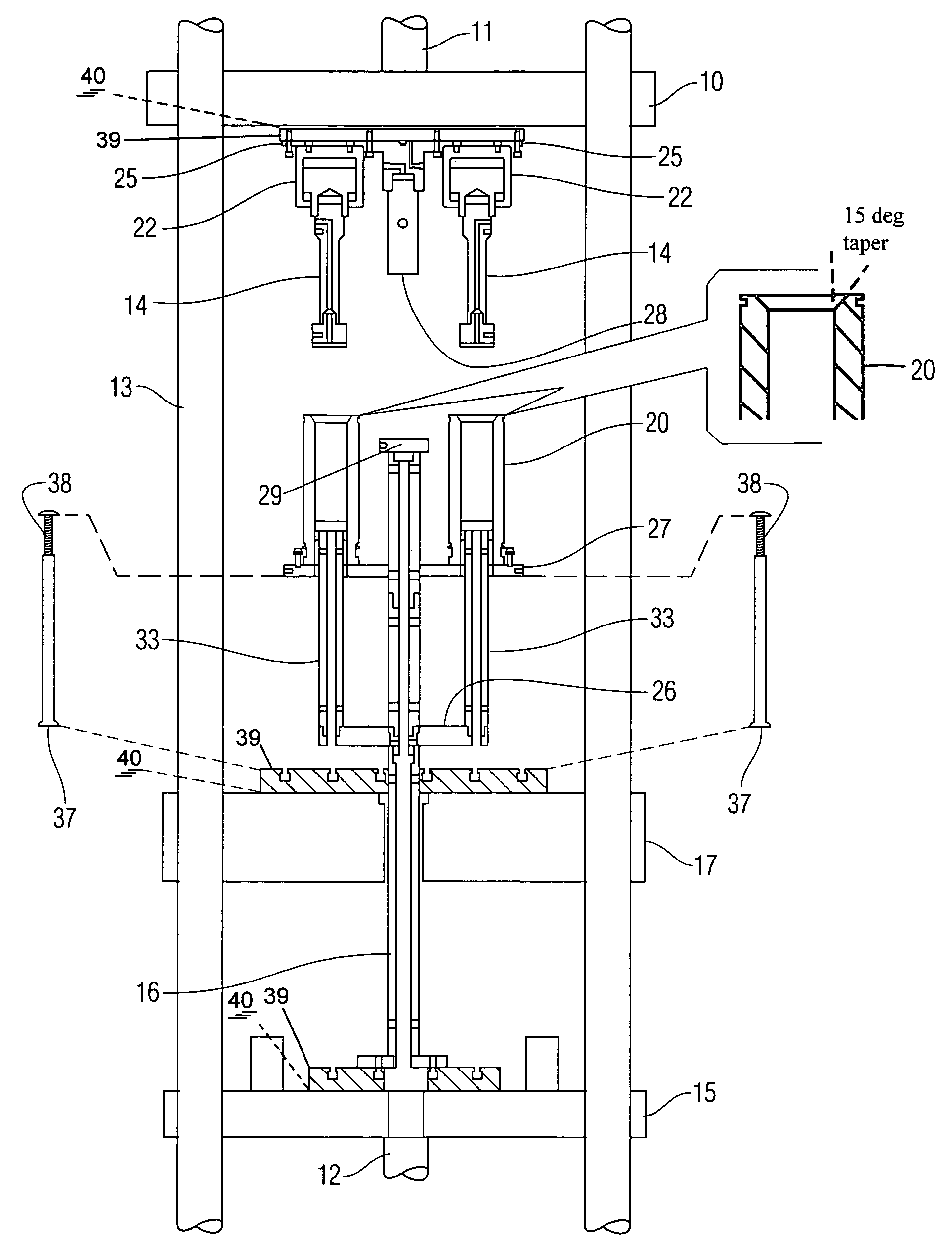
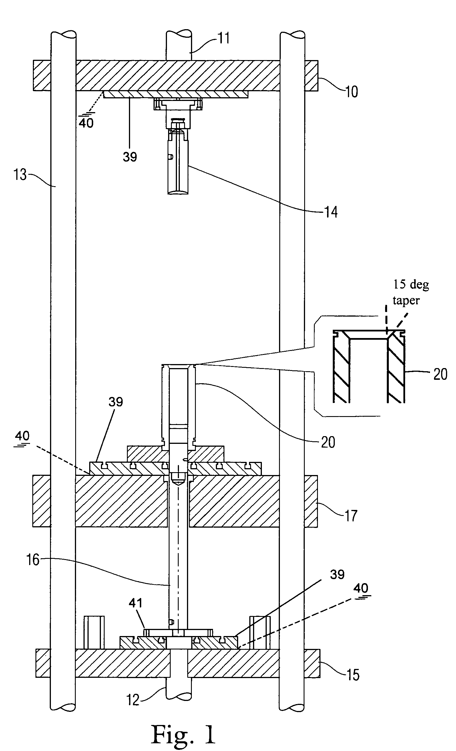
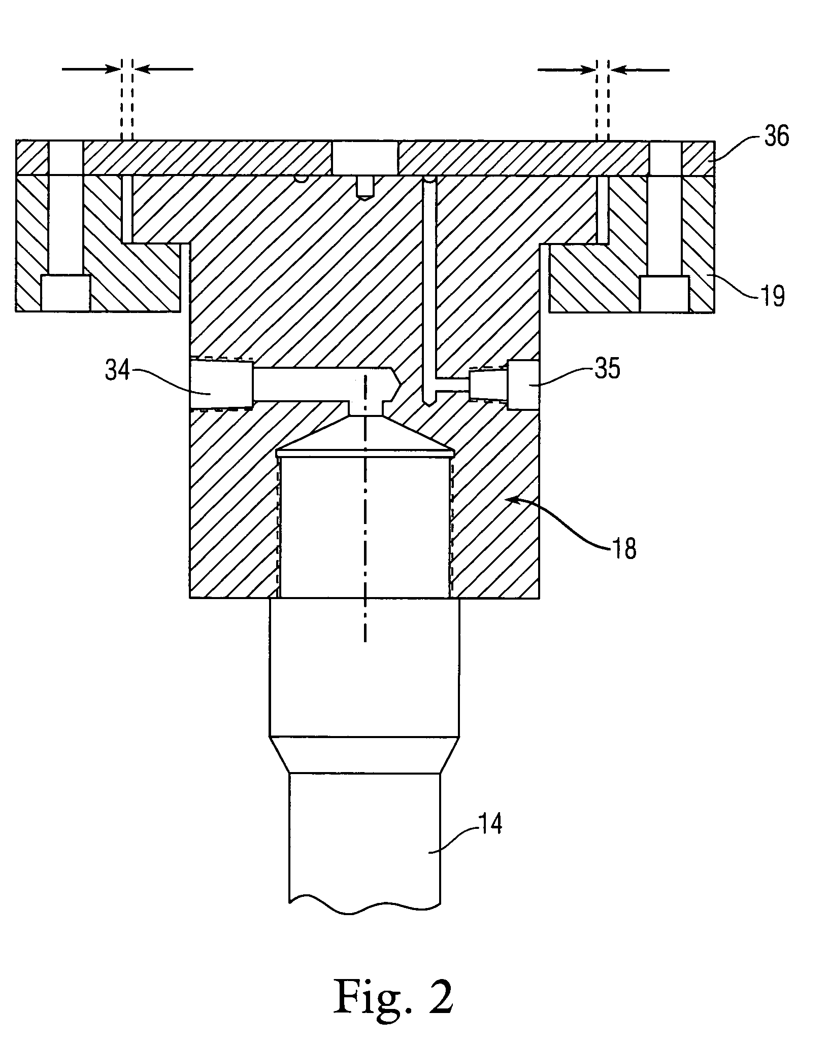
[0017]The modular press assembly according to the present invention is an improvement to a hydraulic press which, when incorporated in number, facilitates multiple position pressing. Each modular press assembly automatically aligns the axes of the press rams and the axes of the dies, and when two or more modular press assemblies are employed they automatically balance the pressing force at their respective press positions, without regard to variations in height of the pressed material. The modular press assemblies may be retrofit to an existing hydraulic press or can be incorporated into the original design of the hydraulic press.

[0018]A conventional hydraulic press is shown in FIG. 1 and has a movable upper platen 10, driven downward by a first hydraulic cylinder 11. The hydraulic press has a movable lower platen 15, driven by a second hydraulic cylinder 12. Four vertical columns 13 rest on a firm support surface and guide the movement of the upper platen 10 and the lower platen 15...


PUM

PropertyMeasurementUnit
degree of freedomaaaaaaaaaa
pressing forceaaaaaaaaaa

Abstract

A modular press assembly for performing multiple position pressing with a single press. The modular press assembly includes a floating mount attached to the upper platen of the press, a hydraulic cylinder, and a press ram coupled to the cylinder which automatically guides itself precisely into axial alignment with a die situated on a lower platen and containing material to be pressed. A plurality of such press assemblies are mounted on the upper platen and are connected through respective flow control valves to an independent hydraulic control system to allow adjustment of the travel of the multiple press rams. This configuration facilitates multiple position pressing and equally divides the total press force from the single hydraulic press, distributing it among each of the multiple positions independent of the final height of each pressed body.

Description

STATEMENT OF GOVERNMENT INTEREST[0001]The invention described herein may be manufactured and used by or for the Government of the United States of America for governmental purposes without payment of any royalties thereon or therefor.BACKGROUND OF INVENTION[0002]a. Field of Invention[0003]The present invention relates to hydraulic presses for compressing materials and, more particularly, to a modular press assembly which can be retrofit to an existing press or supplied as original equipment, in either case allowing multiple batches of material, of differing height, to be compressed with the same force, by the single press, in one operation.[0004]b. Description of the Background[0005]In various industries, it is necessary to prepare a mixture of ingredients in a compact solid body, having uniform size and shape. This is often the case where a measured amount of consumable material must be inserted into a chamber or other container, having a particular shape. Often, the ingredients ar...

Claims


Application Information

Patent Timeline
Patent Type & Authority Patents(United States)
IPC IPC(8): B29C43/04B29C43/58
CPCB29C43/361B29C43/50B30B15/026B30B15/04B30B15/067B29C33/20B29C2043/3283B29C2043/3623B29C2043/503B29C2043/5808B29C2043/5858
Inventor LOWELL, MARK D.GUSACK, JAMES A.
Owner THE UNITED STATES OF AMERICA AS REPRESENTED BY THE SECRETARY OF THE NAVY
Why Eureka
Try Eureka