Receiving/backscattering arrangement and method with two modulation modes for wireless data transmission as well as modulation arrangement therefor

a wireless data transmission and modulation arrangement technology, applied in the direction of phase-modulated carrier systems, instruments, testing/monitoring control systems, etc., can solve the problem that the base station cannot detect the phase-modulated signal reflected from the transponder, the spacing distance between the transponder and the base station becomes smaller, and the power reflected by the transponder decreases, etc. problem, to achieve the effect of high modulation power, adequate radiated power, and efficient amplitude shift key

Active Publication Date: 2006-12-19
ATMEL GERMANY +1
View PDF50 Cites 23 Cited by
  • Summary
  • Abstract
  • Description
  • Claims
  • Application Information

AI Technical Summary

Benefits of technology

[0011]The method according to the invention provides different first and second modulation methods by which the received electromagnetic waves may be modulated and reflected back to the base station. More particularly, depending on the field strength of the electromagnetic waves received by the receiving / backscattering arrangement, the inventive method will use a second modulation method additionally or alternatively to the first modulation method, for modulating and reflecting the received waves back to the base station. This selective or combined use of two different modulation methods achieves a particularly reliable and secure operation of the receiving / backscattering arrangement over a broad distance range, because the two distinct modulation methods can be combined or selected individually so that an optimal or at least sufficient modulation power is provided for every backscattering distance or range, or for every particular data transmission situation.
[0025]In the modulator arrangement according to the invention for carrying out the amplitude shift keying, a rectifier comprises a multi-stage voltage multiplier circuit, and a circuit node of a stage of the voltage multiplier circuit is connected with a controllable switching device, which selectively connects or disconnects the node relative to a reference potential dependent on a control signal applied to the switching device. This makes it possible to achieve an efficient amplitude shift keying, in which the parasitic characteristics of the electronic components of the modulator arrangement do not have an influence in the high frequency region on the input side. Simultaneously, a capacitor that might be used for smoothing the output voltage of the voltage multiplier circuit is loaded only insubstantially or inconsiderably by the switching processes carried out in connection with the modulation.

Problems solved by technology

However, the power reflected by the transponder decreases as the spacing distance between the transponder and the base station becomes smaller.
At very small ranges or distances between the transponder and the base station, it can even occur that the base station can no longer detect the phase-modulated signal reflected from the transponder.

Method used


Image

  • Receiving/backscattering arrangement and method with two modulation modes for wireless data transmission as well as modulation arrangement therefor
  • Receiving/backscattering arrangement and method with two modulation modes for wireless data transmission as well as modulation arrangement therefor
  • Receiving/backscattering arrangement and method with two modulation modes for wireless data transmission as well as modulation arrangement therefor

Examples


second embodiment

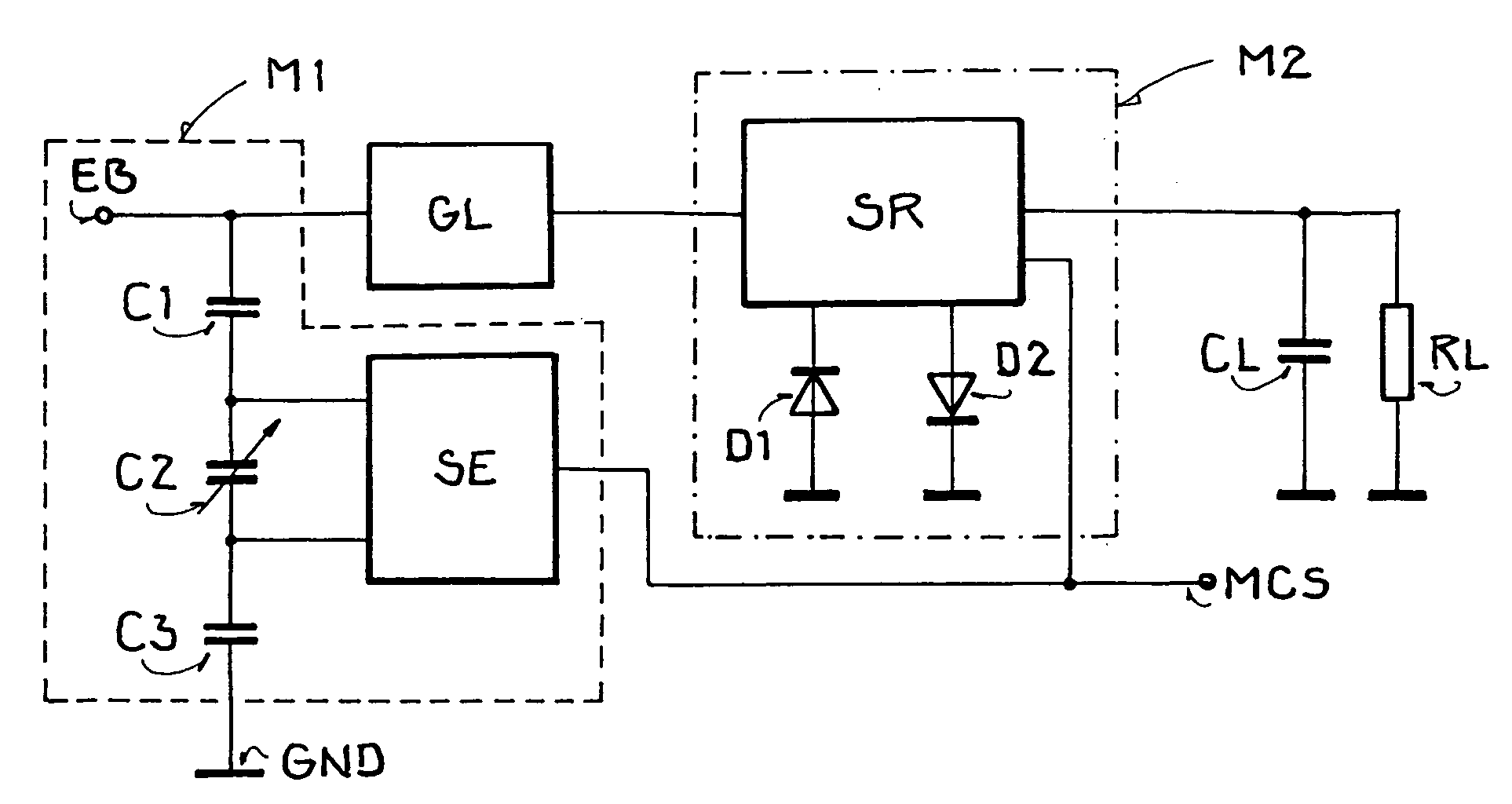
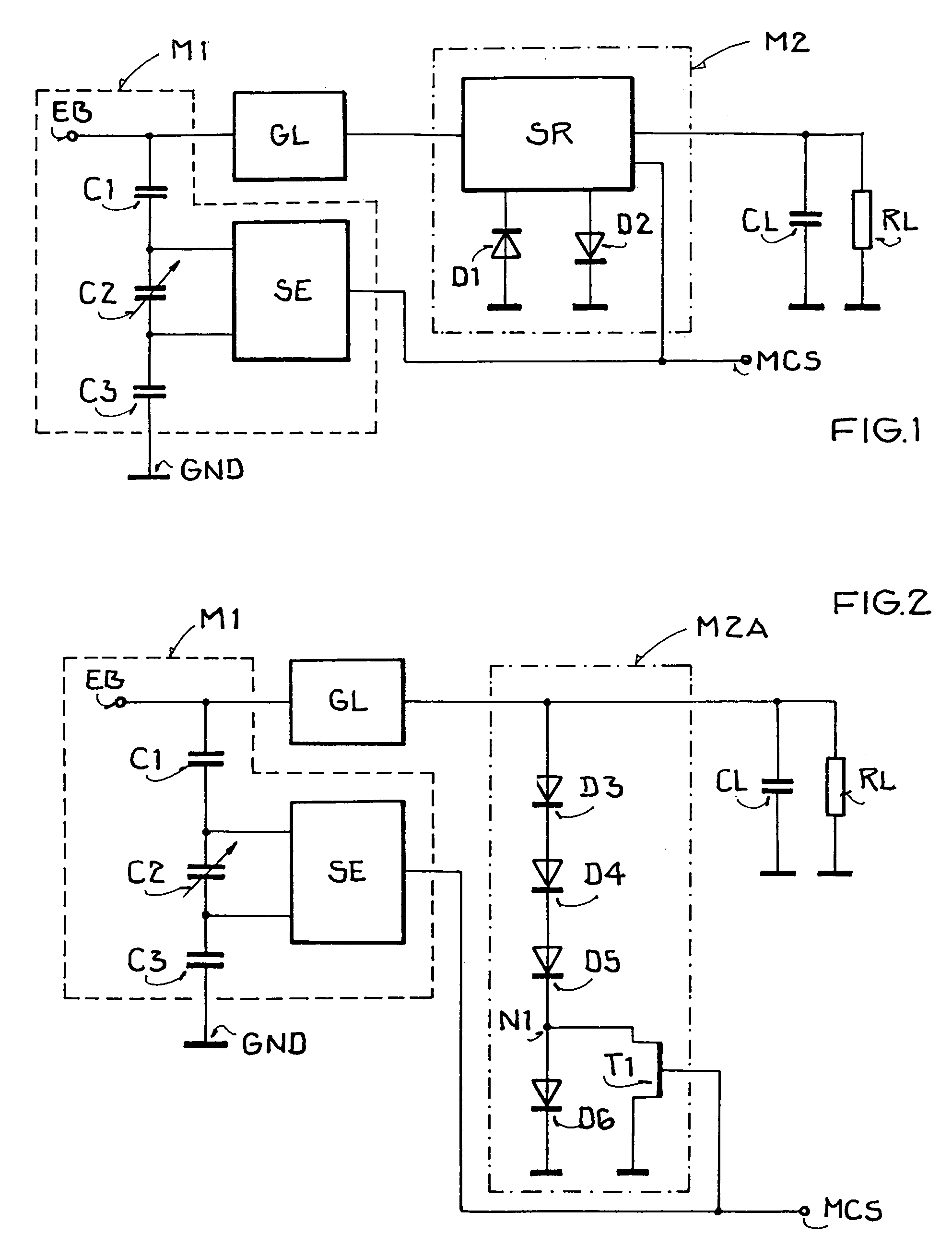
[0044]FIG. 2 shows a receiving / backscattering arrangement according to the invention, in which the amplitude shift keying is achieved using a limiter circuit, of which the working or operating point is adjusted, i.e. varied. The circuit arrangement shown here differs from that according to FIG. 1 only with respect to the embodiment of the second modulator arrangement M2 for carrying out the amplitude shift keying, which is here designated as M2A. The remainder of the inventive arrangement corresponds to that described above in connection with FIG. 1, and will not be redundantly described here.

[0045]The second modulator arrangement M2A comprises diodes D3 to D6 which are connected in a series circuit in the forward conducting or feed direction between a supply voltage, i.e. the output of the rectifier GL, and a reference potential such as ground GND. The second modulator arrangement M2A further comprises a MOS transistor T1 as a switching device, having one terminal of its drain-sour...

third embodiment

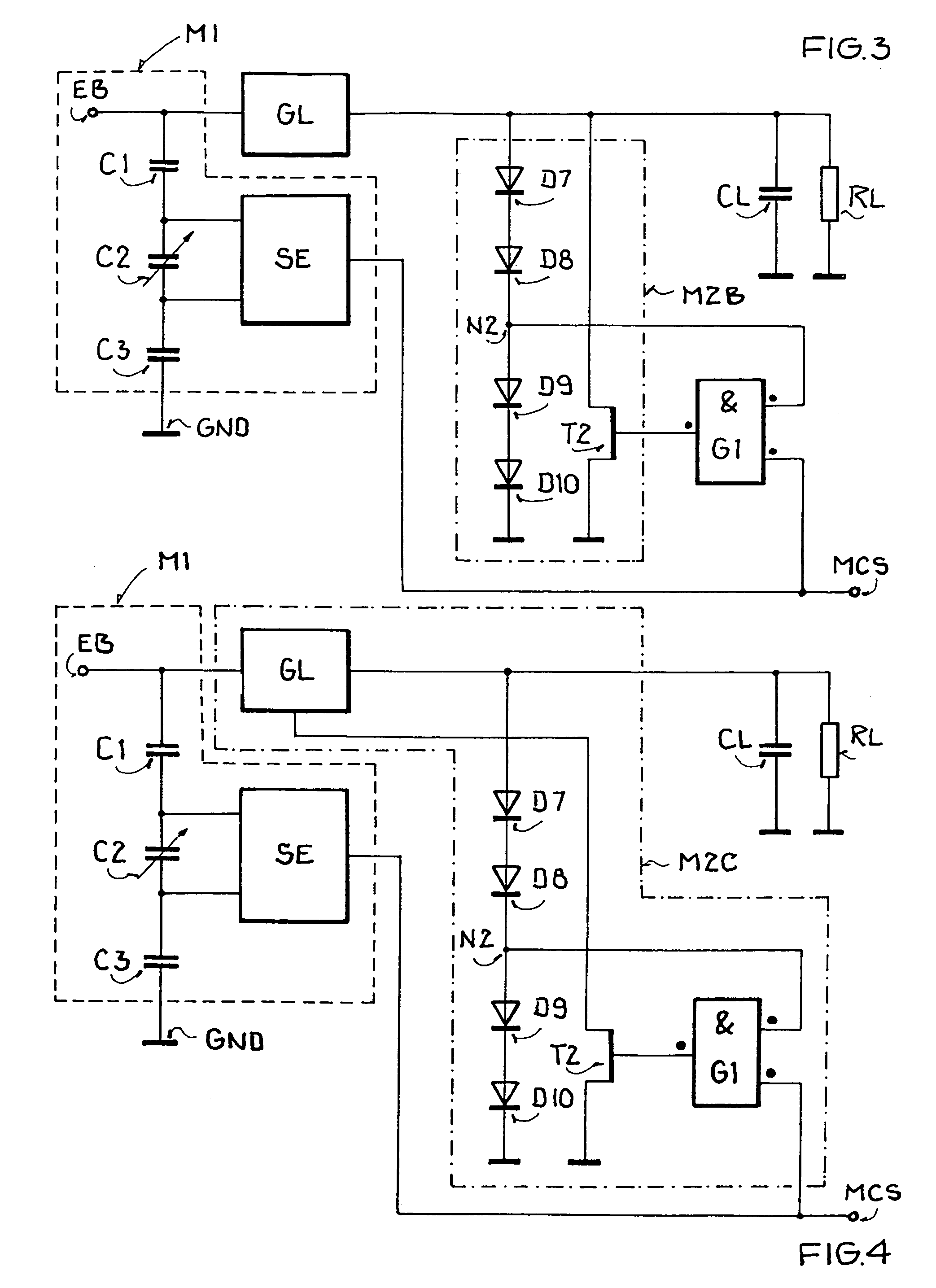
[0048]FIG. 3 shows a receiving / backscattering arrangement according to the invention, in which a series diode circuit or path is used for generating a reference voltage, which serves to release or enable the amplitude shift keying. This embodiment of the arrangement differs from the embodiments described above once again only with respect to the second modulator arrangement M2 for carrying out the amplitude shift keying, which is here designated as M2B. The similar portions of the arrangement in comparison to the above embodiments will not be discussed redundantly here.

[0049]The second modulator arrangement M2B comprises diodes D7 to D10, which are connected in series between the rectifier output voltage and ground, generally similarly as the diodes D3 to D6 in FIG. 2. The second modulator arrangement M2B further comprises a MOS transistor T2, having one terminal of its drain-source path connected to the supply voltage, i.e. the output voltage of the rectifier GL, and having the oth...


PUM


Abstract

For transmitting data, a receiving / backscattering arrangement receives, modulates and reflects or backscatters electromagnetic waves emitted by a base station. The modulation corresponds to the data to be transmitted and is carried out selectively using first and / or second different modulation methods depending on the received field strength of the received electromagnetic waves. Preferably, phase shift keying is used especially or at least at low field strengths at far range, while amplitude shift keying is used additionally or alternatively for high field strengths at close range. The two modulation methods can be superimposed. A circuit arrangement includes two different modulator arrangements to perform the two modulation methods depending on the received field strength. The second modulator arrangement preferably comprises a multi-stage voltage multiplier circuit with a modulated switching device intervening in one of the stages to achieve the modulation.

Description

CROSS-REFERENCE TO RELATED APPLICATIONS[0001]This application is related to U.S. application Ser. No. 10 / 753,849 filed Jan. 7, 2004, U.S. application Ser. No. 10 / 855,865 filed May 26, 2004, and U.S. application Ser. No. 10 / 855,866 filed May 26, 2004.PRIORITY CLAIM[0002]This application is based on and claims the priority under 35 U.S.C. §119 of German Patent Application 103 01 451.9, filed on Jan. 10, 2003, the entire disclosure of which is incorporated herein by reference.FIELD OF THE INVENTION[0003]The invention relates to a method for wireless or contactless data transmission between a base station and a receiving / backscattering arrangement. The invention further relates to a receiving / backscattering arrangement suitable for carrying out this method, as well as to a modulation arrangement that can be used in this regard.BACKGROUND INFORMATION[0004]There are various known systems in which a wireless or contactless data transmission is carried out between one or more base stations ...

Claims


Application Information

Patent Timeline
Patent Type & Authority Patents(United States)
IPC IPC(8): H04Q5/22H04L27/02G06K7/10G06K19/07H03C5/00H04B1/59H04L27/18
CPCG06K7/10861G06K19/0723H03C5/00
Inventor FISCHER, MARTINFRIEDRICH, ULRICH
Owner ATMEL GERMANY
Why Eureka
Try Eureka