Optical component and method of manufacturing the same

a technology of optical components and parts, applied in the field of optical components, can solve the problems of high processing cost, low productivity in the direction of instruments, semiconductor lasers, lenses, etc., and achieve the effects of easy mounting to the lens holder, high reliability, and easy maintenan

Inactive Publication Date: 2006-12-19
NIPPON SHEET GLASS CO LTD
View PDF2 Cites 6 Cited by
  • Summary
  • Abstract
  • Description
  • Claims
  • Application Information

AI Technical Summary

Benefits of technology

[0023]The present invention has been made to solve the foregoing problems. It is an object of the invention to provide a method of mounting a rod lens to a holder easily and with high reliability without requiring machining of the face ends of the lens.
[0025]Because of this configuration, optical characteristics similar to characteristics that would be obtained when the end faces were machined into spherical surfaces are given to the end faces of the rod lens without machining the end faces. In addition, the rod lens can be fixedly mounted to the lens holder easily and with high reliability and high airtightness.
[0027]The transparent member can be easily molded by tapering a part of the through hole in the lens holder. Also, the intimateness between the transparent member and the lens holder can be enhanced.
[0029]After the lens is mounted to the lens holder and the transparent member is molded, the antireflective film or filter can be formed with greater ease than a film formed on a single lens alone.
[0033]This method makes it possible to impart optical characteristics equivalent to characteristics obtained when the end face of the rod lens is machined into a spherical surface to the rod lens without machining the end face of the lens. At the same time, the rod lens can be mounted to the lens holder easily with high reliability and high airtightness.
[0034]According to the present invention, optical characteristics equivalent to characteristics obtained when the end face of the rod lens is machined into a spherical surface can be imparted to the end face of the lens. At the same time, the rod lens can be mounted to the lens holder. Furthermore, formation of an antireflective film or the like can be carried out after the lens is mounted to the holder. Hence, the lens can be easily combined with a semiconductor optical device.

Problems solved by technology

However, machining end faces of rod lenses into spherical surfaces suffers from low productivity.
Especially, where the diameter of a rod lens is reduced, it becomes more difficult to polish the end faces of the lens.
Furthermore, the above-described means (a)–(d) used in mounting the lens to the holder have the following problems.
Consequently, a large number of processing steps are required.
This leads to an increase in the cost.
The method of mounting the lens with an organic adhesive is simple to achieve but the durability has a problem.
In addition, if degassing from the resin occurs, depositions are produced on the surface of the lens or the semiconductor optical device is adversely affected.
In this way, there are many limitations.
Another problem is that press fitting produces internal stress in the glass lens, deteriorating the polarization characteristics.

Method used


Image

  • Optical component and method of manufacturing the same
  • Optical component and method of manufacturing the same
  • Optical component and method of manufacturing the same

Examples


Embodiment Construction

[0043]Preferred embodiments of the present invention are hereinafter described with reference to the drawings.

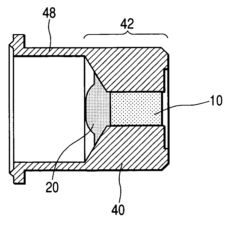
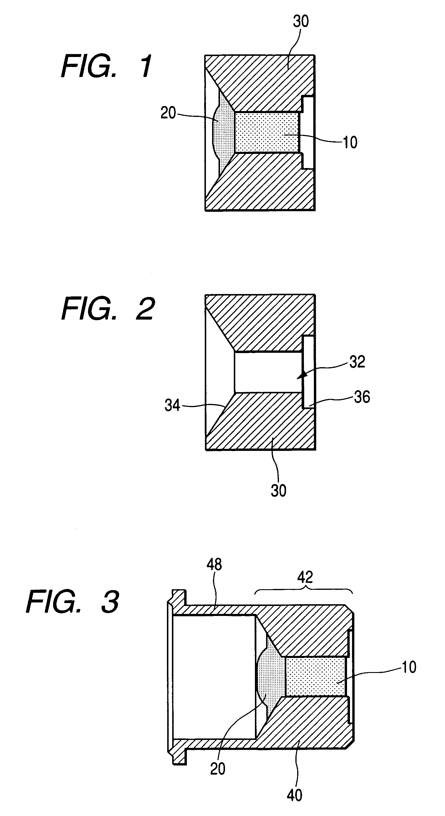
[0044]FIGS. 1 and 3 are cross sections through optical components according to embodiments of the present invention.

[0045]The optical component of the present invention which is shown in FIG. 1 is manufactured by inserting a graded-index rod lens 10 into a cylindrical through hole in a lens holder 30, holding the lens, and molding a lens 20 in tight fitting with one end face of the lens 10.

[0046]As shown in FIG. 2, the lens holder 30 is provided with the through hole having a central portion including a cylindrical portion 32 having a constant diameter substantially coincident with the diameter of the inserted rod lens. One side of the cylindrical portion is a tapering hole 34. The other side 36 of the cylindrical portion is greater in diameter than the body of the cylindrical portion.

[0047]Preferably, the lens holder 30 is so designed that the rod lens 10 passes into the cy...


PUM


Abstract

There is disclosed a method of fixedly mounting a graded-index rod lens to a holder easily with high reliability without requiring machining of one end face of the rod lens which is difficult to achieve if the lens has a small diameter. The present invention also offers an optical component having the graded-index rod lens inserted and fixed in a through hole formed in the holder. A part of the through hole on the side of one end face of the rod lens is formed as a tapering hole. A transparent member is molded so as to be tightly fitted with the holder such that the whole end face of the lens and at least a part of the inner surface of the tapering hole are covered with the transparent member. A part of the surface of the transparent member is shaped spherically or aspherically to form a molded lens.

Description

BACKGROUND OF THE INVENTION[0001]1. Field of the Invention[0002]The present invention relates to an optical component including a holder to which a graded-index rod lens used in the fields of microoptics and optical communications is fixedly mounted.[0003]2. Description of the Related Art[0004]A graded-index rod lens has a capability of refracting light by a refractive index distribution existing in the medium itself and, therefore, the rod lens is fundamentally a cylindrical lens having flat end faces. For this reason, the rod lens shows better geometric matching to other optical elements such as optical fibers compared with general lenses. This is advantageous in making an optical alignment. Furthermore, the medium itself has refractive power and so the focal distance can be varied by varying the lens length. In this way, the rod lens has many excellent characteristics. Consequently, rod lenses of this construction are widely used in the field of microoptics. Also, in the field of...

Claims


Application Information

Patent Timeline
Patent Type & Authority Patents(United States)
IPC IPC(8): G02B6/32G02B3/00G02B6/42G02B7/02H01S5/022
CPCG02B3/0087G02B7/02G02B6/4206G02B6/4204
Inventor TANAKA, HIROYUKI
Owner NIPPON SHEET GLASS CO LTD
Why Eureka
Try Eureka