System for reducing powertrain reaction torque

a technology of reaction torque and powertrain, which is applied in the field of system control of powertrain, can solve the problems of large inertia, difficult to solve problems, and often considerable effective inertia of powertrains, and achieve the effect of reducing these inertial forces

Active Publication Date: 2006-12-19
FORD GLOBAL TECH LLC
View PDF12 Cites 13 Cited by
  • Summary
  • Abstract
  • Description
  • Claims
  • Application Information

AI Technical Summary

Benefits of technology

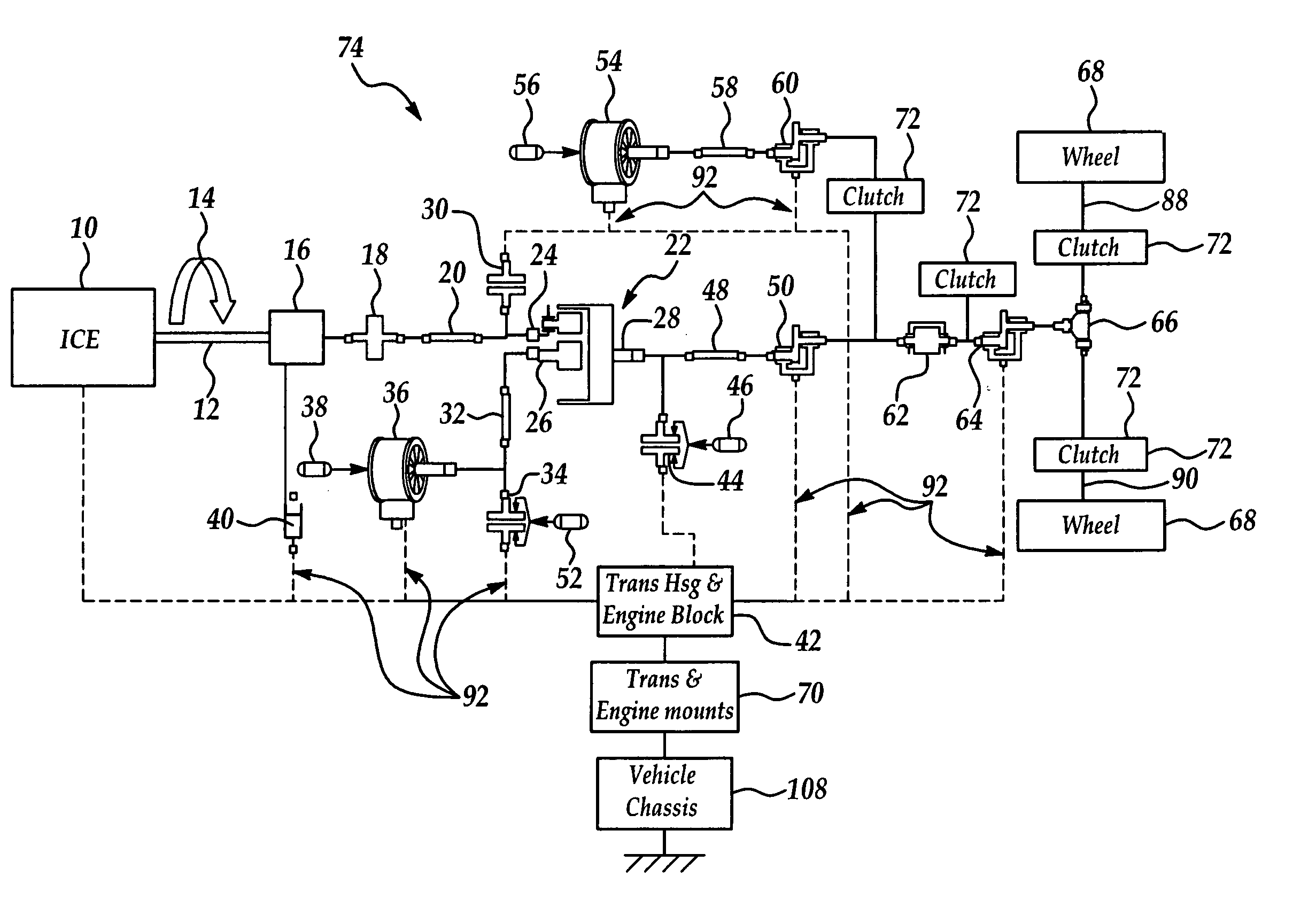
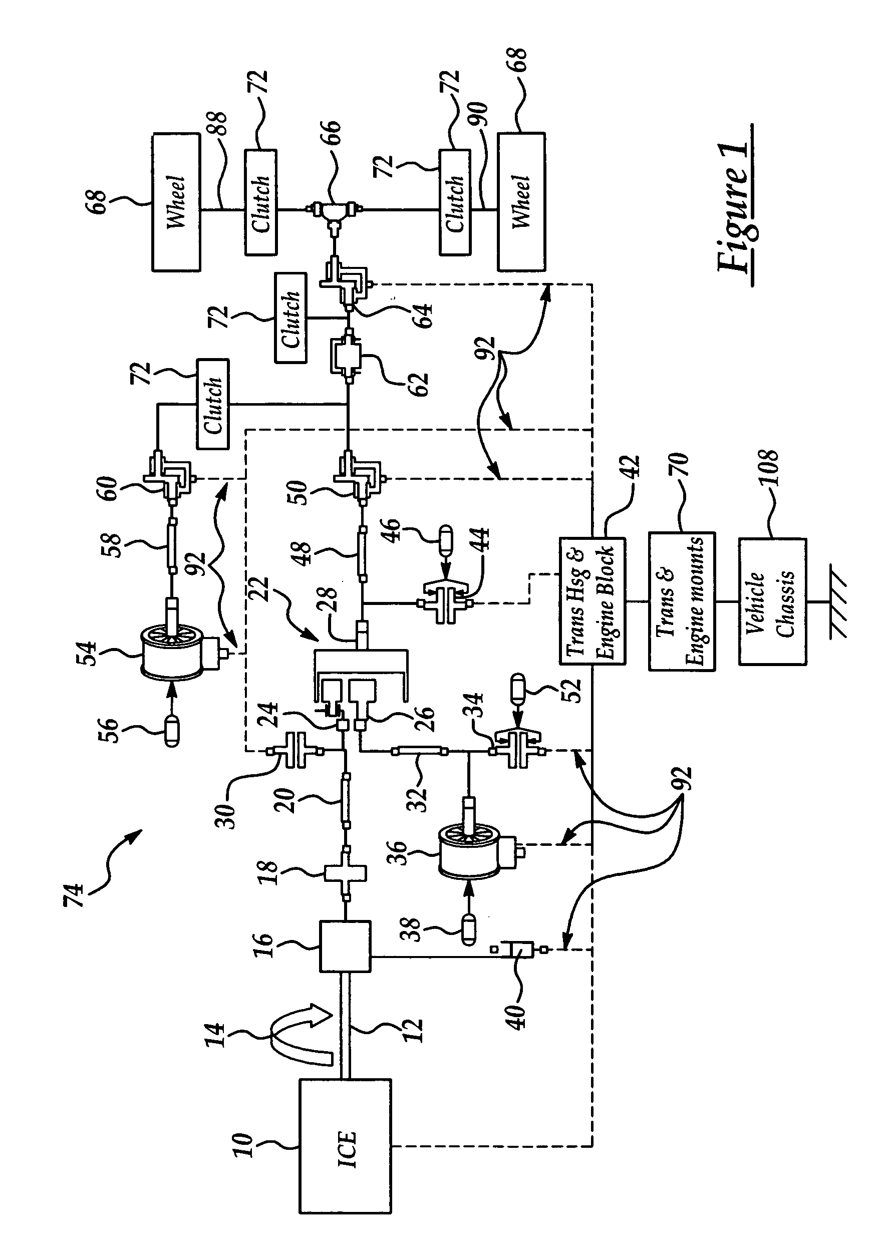
[0006]A system is provided for controlling inertial forces within a vehicle powertrain during certain operating conditions, such as sudden braking events. The control system reduces these inertial forces through the use of relatively simple powertrain components such as clutches and existing vehicle sensors. A further advantage of the present system resides in its compatibility with a wide range of HEV configurations and powertrain geometries.

Problems solved by technology

As a result, HEV powertrains often possess considerable effective inertia at the wheels compared to conventional ICE powertrains.
This is due in part to the potentially large inertia of the hybrid motor devices, as well as the significant gearing from motor to wheels that is often employed.
Powertrains possessing relatively high effective inertias such as those of HEVs, result in certain problems that require solutions.
For example, the application of braking force to the vehicle's traction wheels during a sudden braking event, may result in a very rapid angular momentum change in the powertrain.
Specifically, a rapid deceleration of the traction wheels during braking results in a counter-torque being transmitted from the traction wheels back through the driveline.
This reaction torque is transmitted through the gearing mechanisms to the transmission housing, and can have deleterious effects on powertrain and driveline components, particularly under sudden conditions, such as when the vehicle's ABS system is activated.

Method used


Image

  • System for reducing powertrain reaction torque
  • System for reducing powertrain reaction torque
  • System for reducing powertrain reaction torque

Examples


Embodiment Construction

[0015]FIG. 4 shows a generic architecture for a hybrid vehicle system 134, to which the present invention may be applied. The system 134 includes a primary power source 114, such as a gasoline, diesel or other gas fuel supply, coupled to a primary power generating system 116, such as an internal combustion engine. The primary power generating system 116 generates a primary drive torque that is transmitted to the vehicle's driveline 132 via power transmission assembly 118. The power transmission assembly 118 can be a conventional manual, automatic or continuously variable automotive transmission, or other equivalent gearing mechanism for transmitting mechanical power produced by the primary power generating system 116. The system 134 further includes a secondary power source 120, such as a battery, ultracapacitor, hydraulic accumulator or other energy storage device, and secondary power generating system 122, such as one or more electric machines or other torque generating devices, f...


PUM


Abstract

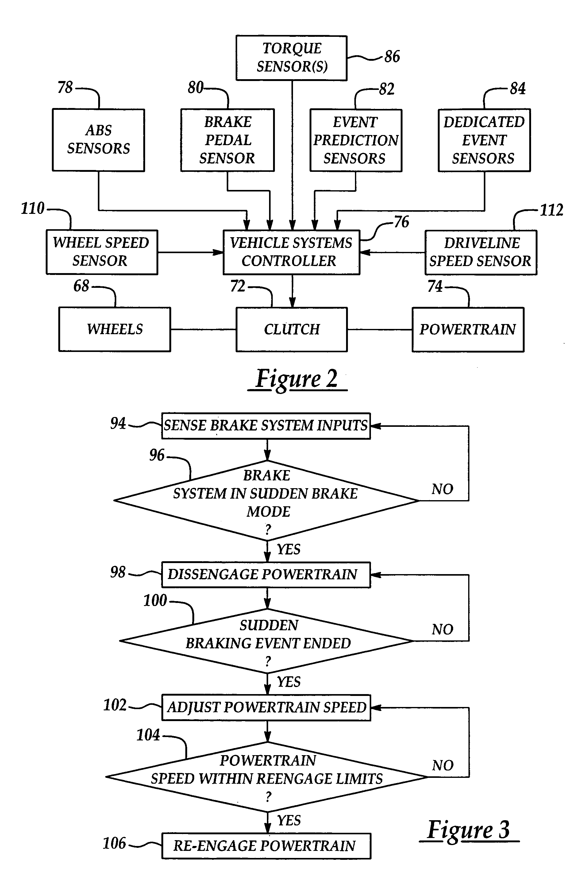
A system is provided for controlling the inertia of a vehicle's powertrain during sudden braking events. Torque generated by rapid deceleration of the vehicle's drive wheels during braking is prevented from being transmitted through the vehicle's driveline by a clutch which disengages the drive wheels from high effective inertia components in the driveline. The clutch is actuated by a signal produced by any of several sensors on the vehicle which sense a sudden braking event. Driveline speed is adjusted to match drive wheel speed before the clutch is deactivated to reengage driveline with the drive wheels.

Description

FIELD OF THE INVENTION[0001]This invention generally relates to vehicle powertrains, and deals more particularly with a system for controlling powertrains having high inertias and reaction torques.BACKGROUND OF THE INVENTION[0002]Environmental concerns and the need for fuel conservation has spurred the development of new hybrid propulsion systems for vehicles. Hybrid electric vehicle (HEV) powertrains for example, typically include electric traction motors, high voltage electric energy storage systems, and modified transmissions. Electric energy storage systems include batteries and ultra capacitors. Primary power units for these systems may include spark ignition engines, compression ignition direct injection (e.g., diesel) engines, gas turbines and fuel cells.[0003]HEV powertrains are typically arranged in series, parallel or parallel-series configurations. With parallel-series arrangements, multiple motors operating in multiple operating modes sometimes require the use of several...

Claims


Application Information

Patent Timeline
Patent Type & Authority Patents(United States)
IPC IPC(8): G06F19/00B60K17/00B60T8/32B60W10/02B60W30/18F16D48/00
CPCB60K6/48B60T8/3215B60W10/02B60W10/11B60W30/18109B60W10/184B60T2201/09Y10T477/70B60W2520/28Y02T10/6221Y02T10/84Y02T10/62
Inventor TOBLER, BILLTILLER, MICHAELBOWLES, PAUL
Owner FORD GLOBAL TECH LLC
Why Eureka
Try Eureka