Commercial aircraft on-board inerting system

a fuel tank and aircraft technology, applied in the field of commercial aircraft fuel tank inerting system, can solve the problems of high probability of explosion, complex and unreliable components, increased likelihood of flame initiation and propagation, etc., and achieves the effects of reducing flammability, minimizing system size and weight, and high flammability

Active Publication Date: 2006-12-26
THE BOEING CO
View PDF19 Cites 83 Cited by
  • Summary
  • Abstract
  • Description
  • Claims
  • Application Information

AI Technical Summary

Benefits of technology

[0010]The embodiments of the present invention provide several advantages. One such advantage is the provision of an inerting system that reduces the flammability of high flammability tanks, such as aircraft center tanks where flammability is generally the highest, thus minimizing system size and weight.
[0012]Furthermore, another advantage provided by an embodiment of the present invention is the provision of an inerting system that maintains oxygen content levels within fuel tanks of an aircraft to approximately 12% or less. In so doing, the present invention minimizes weight, size, and cost of an inerting system and provides improved reliability and operational performance.
[0013]Yet another advantage provided by an embodiment of the present invention is the provision of producing inerting gas by utilizing bleed air pressure without the additional need for a compressor, thereby further minimizing weight and maximizing the reliability of an inerting system. Note although there is no additional need for a compressor, the stated embodiment may utilize a compressor when desired.
[0014]Moreover, another embodiment of the present invention minimizes the quantity of bleed air used during climb and cruise by operating in multiple inerting system modes. The present invention also utilizes an ozone converter to enhance air separation module reliability and life.
[0015]In addition, another embodiment utilizes the inerting gas provided to the tanks to supply an ejector that mixes the tank air / vapor volume, which minimizes oxygen content variation throughout the tanks.

Problems solved by technology

Fuel tanks within wings of an aircraft represent vulnerable areas on all aircraft for the potential for flame initiation due to the existence of fuel vapor and oxygen concentration levels therein.
As is known in the art, as oxygen concentration levels within a fuel tank increase, likelihood of flame initiation and propagation and likelihood of a possible explosion also increases.
This threat exists since fuel vapors generally mix with ambient air that has a 21% concentration of oxygen.
Military inerting systems often utilize complicated and unreliable components to provide nitrogen-enriched air to each wing fuel tank, for all perceivable mission conditions.
During combat military missions, threats from hostile munitions are highly probable.
The military type systems have a poor reliability history, with high maintenance costs and are oversized for the vast majority of typical commercial aircraft operations.

Method used


Image

  • Commercial aircraft on-board inerting system
  • Commercial aircraft on-board inerting system
  • Commercial aircraft on-board inerting system

Examples


Embodiment Construction

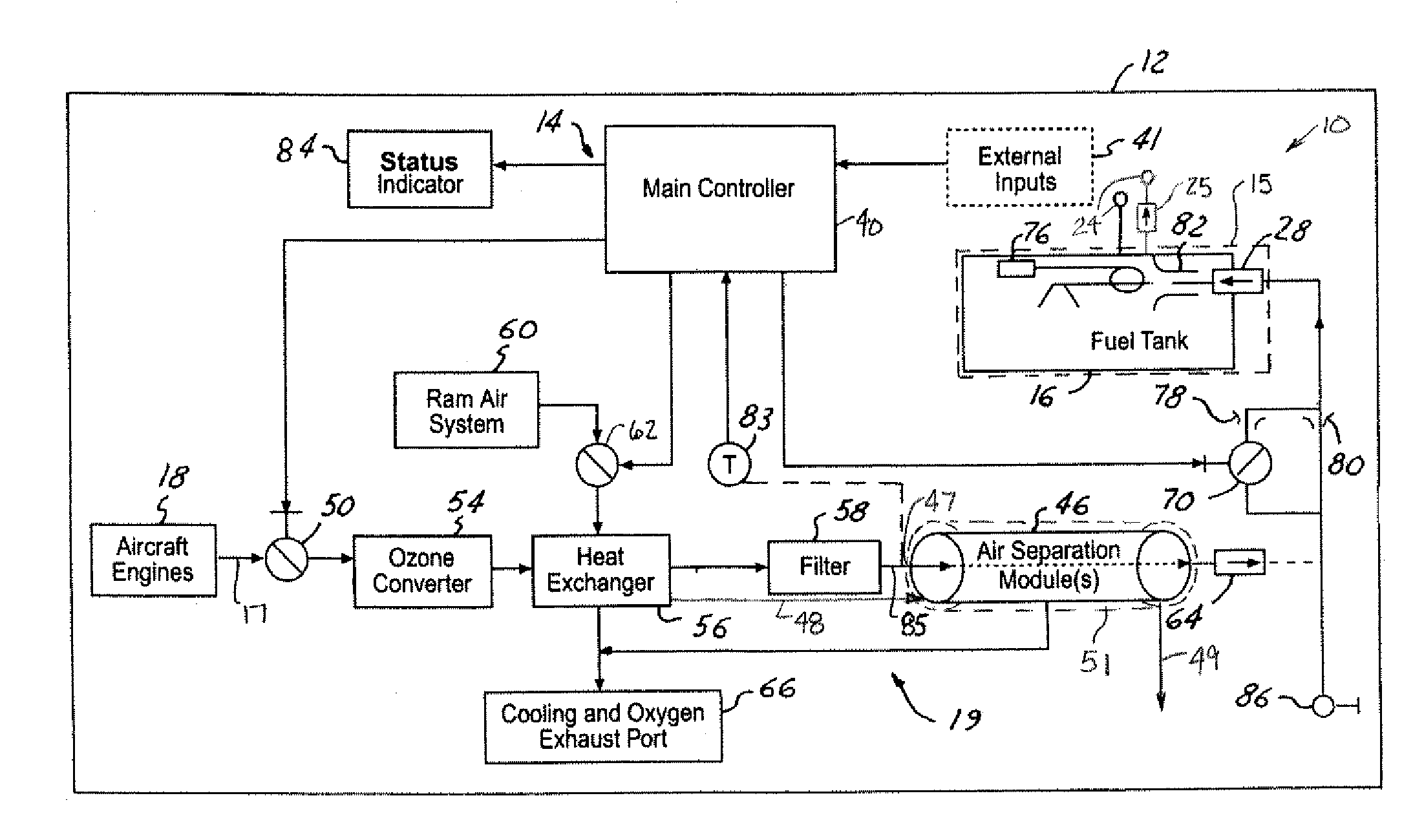
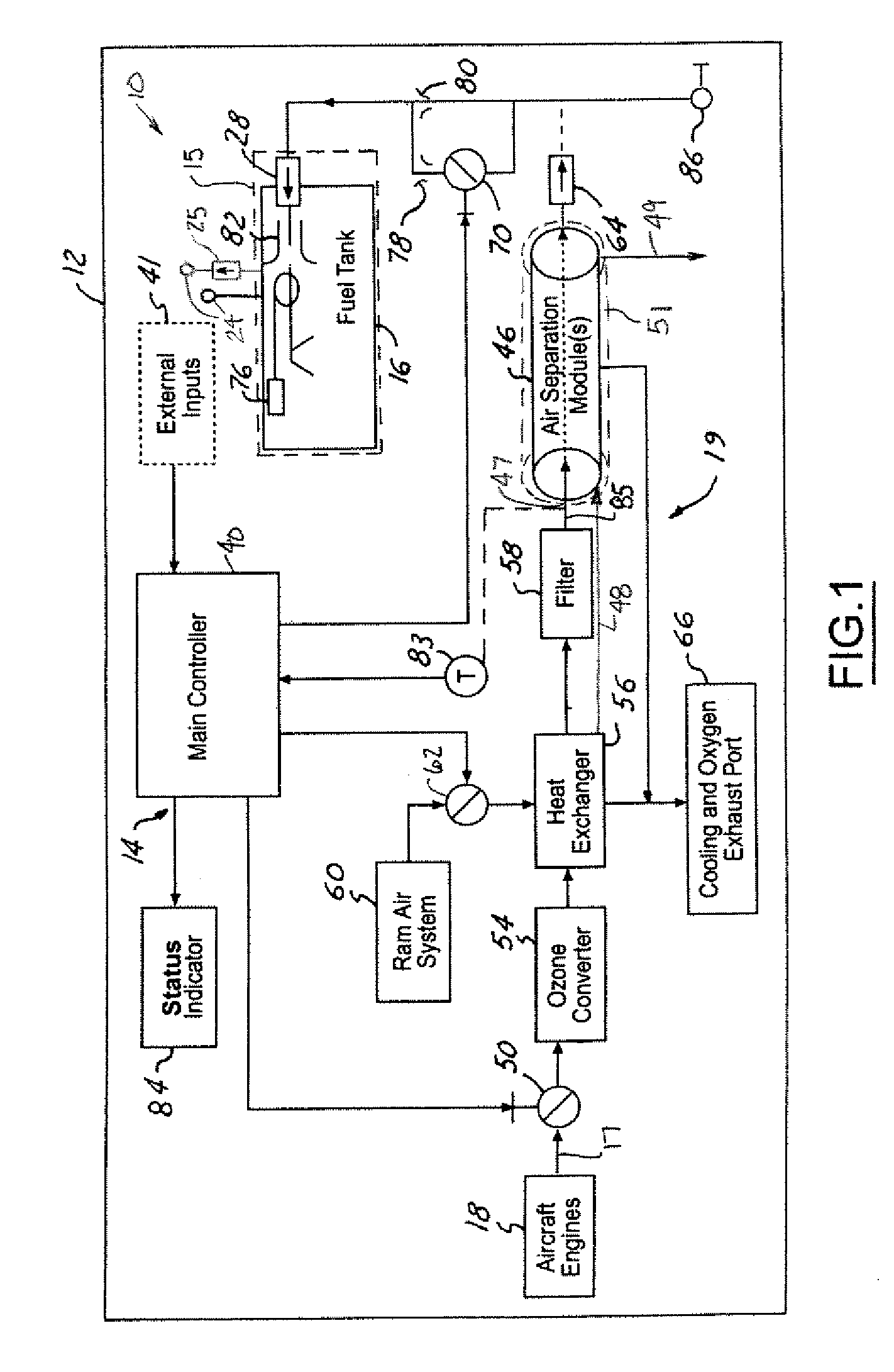
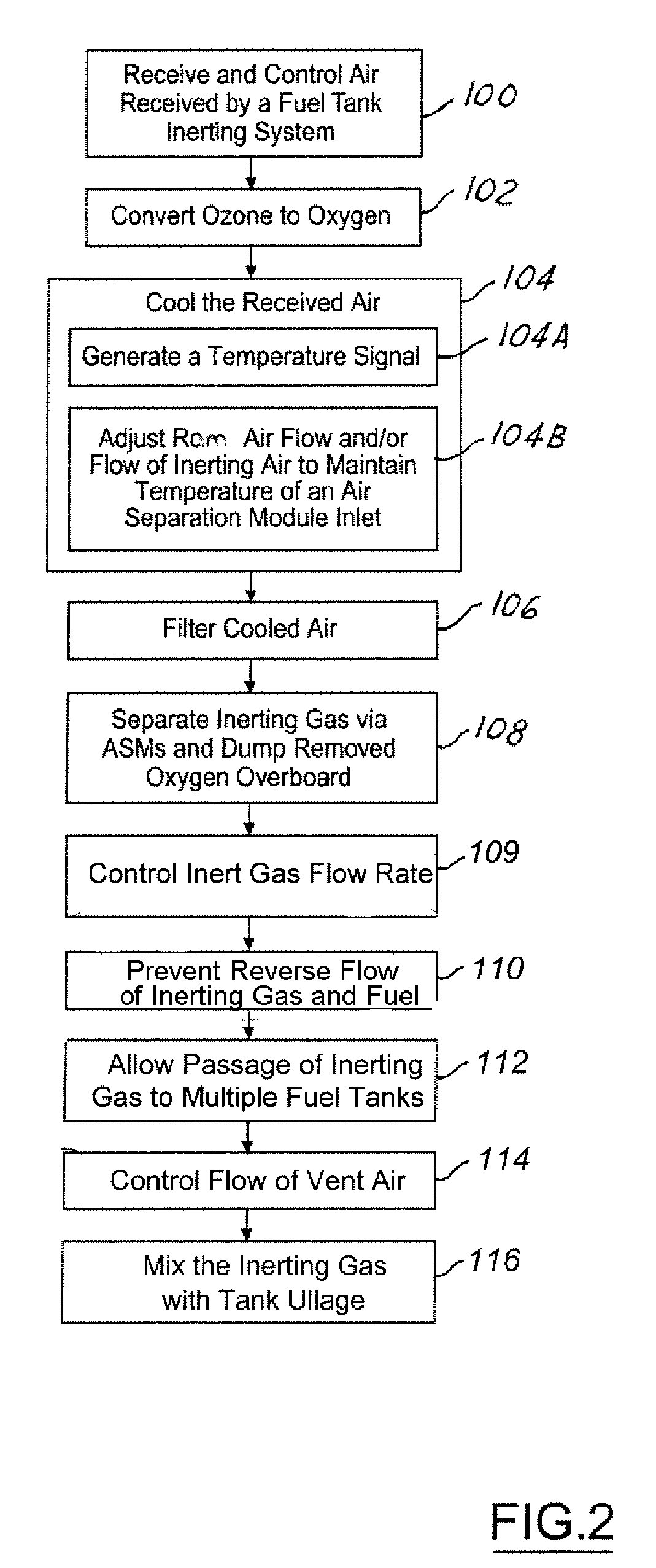
[0019]In each of the following figures, the same reference numerals are used to refer to the same components. While the present invention is described with respect to a system and method for supplying inerting gas to center fuel tanks during ground and / or flight conditions of an aircraft, the present invention may be adapted for various inerting system applications known in the art.

[0020]In the following description, various operating parameters and components are described for one constructed embodiment. These specific parameters and components are included as examples and are not meant to be limiting.

[0021]Referring now to FIG. 1, a block diagrammatic and schematic view of an on-board inerting system 10 for an aircraft 12 in accordance with an embodiment of the present invention is shown. The inerting system 10 includes an on-board inerting control circuit 14, which controls supply of inerting gas to one or multiple fuel tank circuits 15 (only one is shown). The control circuit ut...


PUM

PropertyMeasurementUnit
flow rateaaaaaaaaaa
temperatureaaaaaaaaaa
inlet temperatureaaaaaaaaaa

Abstract

An inerting system (10) for an aircraft (12) includes one or more fuel tank circuits (15) associated with fuel tanks (16). An air source (17) supplies pressurized air. A heat exchanger (56) cools the pressurized air. An air separation module (46) is in fluid communication with the heat exchanger (56) and separates inerting gas from the pressurized air. A controller (40) controls flow of the inerting gas from the air separation module (46) to the fuel tanks (16).

Description

BACKGROUND OF INVENTION[0001]The present invention relates generally to aeronautical vehicle fuel tank inerting systems, and more particularly, to a system for inerting fuel tank(s) of a commercial aircraft.[0002]Fuel tanks within wings of an aircraft represent vulnerable areas on all aircraft for the potential for flame initiation due to the existence of fuel vapor and oxygen concentration levels therein. Fuel tank inerting systems are currently used to reduce oxygen concentration levels within fuel tanks of some military aircraft in order to significantly reduce the vulnerability of military aircraft to hostile munitions.[0003]As is known in the art, as oxygen concentration levels within a fuel tank increase, likelihood of flame initiation and propagation and likelihood of a possible explosion also increases. This threat exists since fuel vapors generally mix with ambient air that has a 21% concentration of oxygen. It has been determined that when oxygen concentration levels are m...

Claims


Application Information

Patent Timeline
Patent Type & Authority Patents(United States)
IPC IPC(8): B65B31/04B64D37/32
CPCB64D37/32B64D2013/0677A62C3/06A62C3/08
Inventor MORAVEC, BRADFORD L.BOGGS, ROYAL E.GRAHAM, RODNEY N.GRIM, ALANADKINS, DAVID A.SNOW, JR., DONALDHAACK, GREG A.
Owner THE BOEING CO
Why Eureka
Try Eureka