Automated guided vehicle

a guided vehicle and automatic technology, applied in the direction of packaging goods, charge manipulation, furnaces, etc., can solve the problems of no possibility for the wafer to jump out from the opening by defying gravity, and large possibility for the wafer to jump ou

Inactive Publication Date: 2006-12-26
MURATA MASCH LTD +1
View PDF11 Cites 10 Cited by
  • Summary
  • Abstract
  • Description
  • Claims
  • Application Information

AI Technical Summary

Problems solved by technology

However, if the automated guided vehicle is advanced or receded with the buffer cassette in the horizontal state, there is a possibility for the wafer to jump out from the opening of the buffer cassette by inertia.
In particular, at starting and at stopping, since a change in a traveling speed of the automated guided vehicle is large, the possibility for the wafer to jump out is large.
Therefore, there is no possibility for the wafer to jump out from the opening by defying gravity.
However, such a structure is large scaled, and causes a great increase in a manufacturing cost of the automated guided vehicle.
Therefore, there were problems that when the pressing member contacts against the edge of the wafer, the pressing member is damaged, and in extreme cases, the pressing member is cut.
Therefore, when a number of wafers Wb·Ws stored in the upper and lower cassettes 1111·1112 is small, the pressing force of the pressing means 1102 applied to each of the wafers Wb·Ws is excessive, and there is a possibility for the wafers Wb·Ws to be damaged.
As a result, an extremely large number of cassettes become neces

Method used


Image

  • Automated guided vehicle
  • Automated guided vehicle
  • Automated guided vehicle

Examples


second embodiment

[0089]Next, the present invention will be described with reference to the accompanying drawings.

[0090]First, a structure of the automated guided vehicle of the second embodiment will be described briefly.

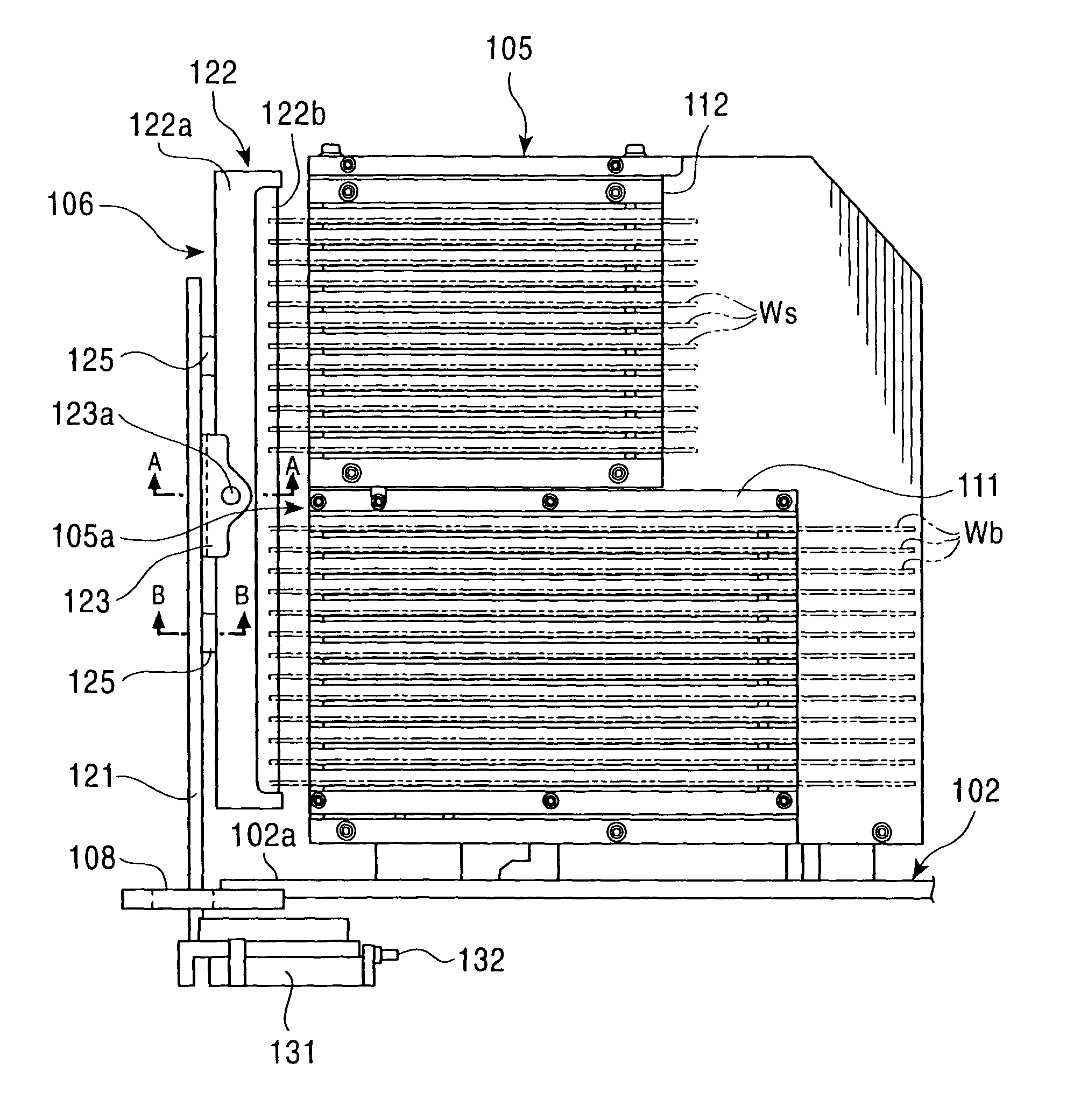
[0091]In the automated guided vehicle 101 shown in FIG. 6, a buffer cassette 105 which can store a plurality of wafers Wb·Ws formed from a silicon single crystal or the like, a pressing means 106 of the wafers Wb·Ws, a transfer equipment 103 which transfers the wafers Wb·Ws, and a positioning device 104 which adjusts a direction, a position or the like of the wafers Wb·Ws, are provided in an upper part of a main body 102 which can travel by wheels 109·109 . . . . The automated guided vehicle 101 transports the wafers Wb·Ws stored in the buffer cassette 105 to a prescribed destination. Then, the wafers Wb·Ws are transferred one sheet at a time to a processing equipment or a stocker provided at the destination by the transfer equipment 103 formed as a single wafer transfer equipment.

[...

third embodiment

[0110]Next, the present embodiment will be described.

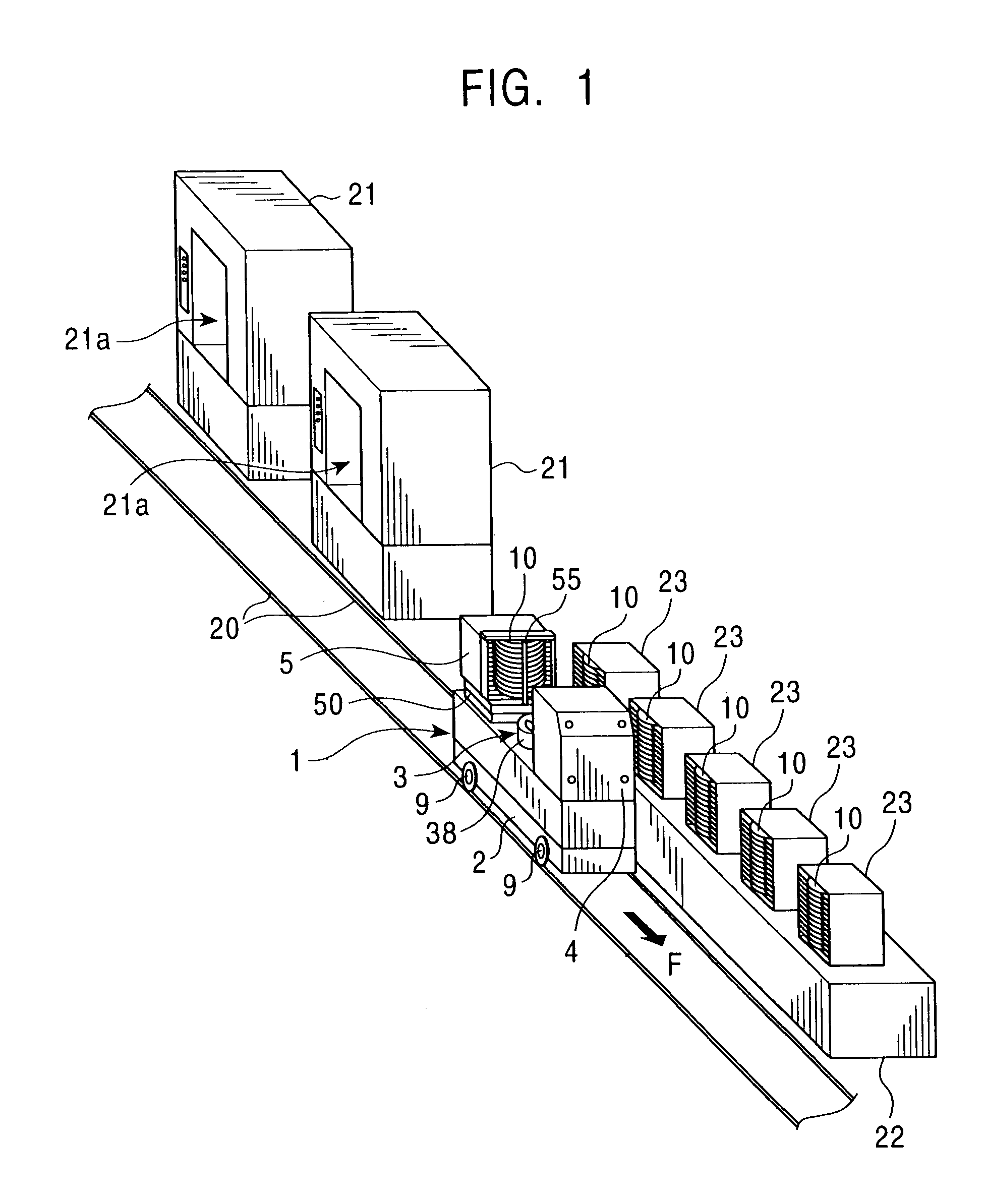
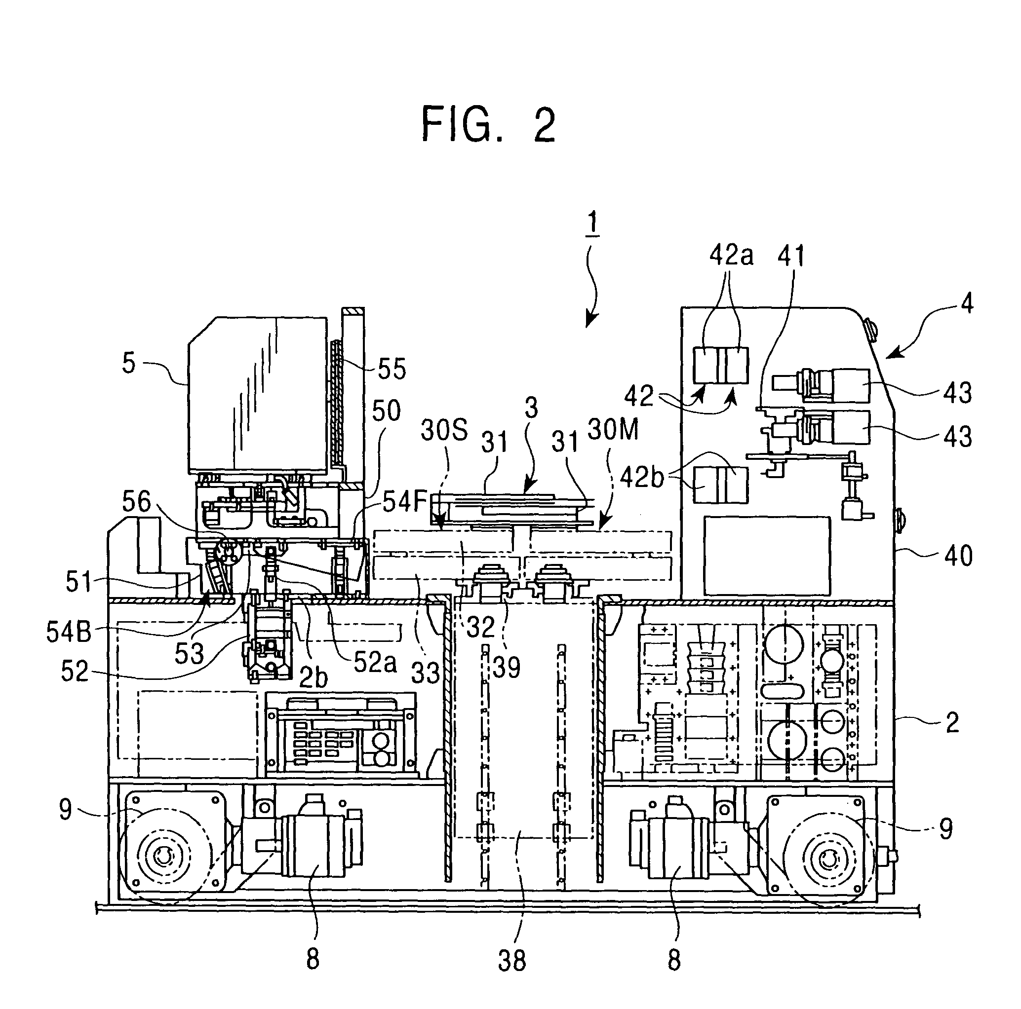
[0111]First, the entire structure of an automated guided vehicle 201 of the third embodiment will be described with reference to FIG. 15 and FIG. 16. Further, from the aspect of the present invention, an embodiment of the present invention can be applied to an automated guided vehicle which does not have traveling rails and which is guided by a guide wire or a laser guide device.

[0112]The automated guided vehicle 201 is a track guided vehicle which travels on two traveling rails 202·202 laid in a clean room. The automated guided vehicle 201 is supplied with electricity in a non-contacting state by an electric supply line (not shown in the drawings) provided in one of the traveling rails 202, and the electricity is supplied to drive motors 204·204 . . . which drives traveling wheels 203·203 . . . . A buffer cassette table 206 is provided on a rear part of the upper surface of the automated guided vehicle 201. The buffer cassette 20...


PUM


Abstract

In an automated guided vehicle including a transfer equipment which transfers a wafer, a buffer cassette which temporarily stores the wafer, and a pressing member which is provided at an opening of the buffer cassette, when traveling the automated guided vehicle, if the pressing member is slid to a center position from an end position of the opening of the buffer cassette to contact and press against the edge of the wafer, the pressing member was easily damaged by being rubbed against a periphery of the wafer, and there was a problem in durability of the pressing member.
The pressing member 55 can transfer between a “pressing” position which contacts against the edge of the wafer 10 to press the wafer 10, and a “receding” position which is located away from the edge of the wafer 10. A transferring direction A of the pressing member 55 of a moment in which the pressing member 55 contacts against the edge of the wafer 10 when the pressing member 55 transfers from the “receding” position to the “pressing” position, is approximately perpendicular to an outline of the part of the wafer 10 contacted against the pressing member 55.

Description

FIELD OF THE INVENTION[0001]The present invention relates to an automated guided vehicle which automatically transports and transfers a semiconductor wafer between stations in a semiconductor manufacturing plant.DESCRIPTION OF THE RELATED ART[0002]Conventionally, in the semiconductor manufacturing plant where a generation of dust becomes a problem, a technology is being considered for transferring and transporting the semiconductor wafer by automatically traveling an automated guided vehicle having a scalar arm typed robot and a buffer cassette which temporarily stores the wafer. When loading the wafer to the automated guided vehicle, first, the automated guided vehicle moves to a front of an automatic warehouse or the like. Then, the robot takes out the wafer from the automatic warehouse or the like one sheet at a time. The robot is inserted from an opening of the buffer cassette, and the wafer is stored to one of a plurality of bins formed in the buffer cassette. The bins formed i...

Claims


Application Information

Patent Timeline
IPC IPC(8): B65G1/07H01L21/68B65G49/07H01L21/00H01L21/673H01L21/677
CPCH01L21/67092H01L21/67265H01L21/67724H01L21/67763H01L21/681H01L21/6835H01L21/673H01L21/6735B65G49/07
Inventor MIYANO, KENMURAYAMA, TAKAHIKONAKAO, TAKASHIAKIYAMA, SHUJI
Owner MURATA MASCH LTD
Why Eureka
Try Eureka