Magnetic return path and permanent-magnet fixing of a rotor

a permanent magnet and return path technology, applied in the direction of magnetic circuit rotating parts, dynamo-electric machines, magnetic circuit shape/form/construction, etc., can solve the problems of increasing relative inaccuracy, inability to produce permanent magnets, and inability to accurately position

Inactive Publication Date: 2006-12-26
ROBERT BOSCH GMBH
View PDF5 Cites 10 Cited by
  • Summary
  • Abstract
  • Description
  • Claims
  • Application Information

AI Technical Summary

Benefits of technology

[0009]The fixation elements have the advantage that they compensate for production tolerances of the permanent magnets. Since the fixation elements fix one permanent magnet on sides remote from one another of the permanent magnet and in particular firmly clamp it, they position the permanent magnet centrally between them regardless of its production tolerance.
[0010]Another advantage is that the fixation elements keep the permanent magnets of the rotor positioned during the adhesive bonding, potting or spraying until an adhesive, plastic or synthetic resin has cured. Upon insertion of the rotor into a guard tube as well, the fixation elements keep the permanent magnets positioned.
[0011]An additional advantage of the fixation elements is that they contribute to a transmission of moment and offer protection against displacement in the event of a mechanical defect of the electrical machine.
[0026]The foregoing relates to preferred exemplary embodiments of the invention, it being understood that other variants and embodiments thereof are possible within the spirit and scope of the invention, the latter being defined by the appended claims.
[0012]According to one embodiment the short-circuit element has laminations rotated relative to one another, between whose spring elements various permanent magnets are firmly clamped. The laminations are rotated relative to one another by 360°, divided by the number of permanent magnets or a multiple of that number. Because of the contrary rotation of the laminations it is possible to provide fewer pairs of spring elements for one lamination than the rotor has permanent magnets. For instance, pairs of spring elements may be provided for alternate permanent magnet in one lamination. This is advantageous or necessary if it is difficult or impossible to provide pairs of spring elements on one lamination for all the permanent magnets, for reasons of space. Moreover, the contrary rotation of the laminations has the advantage that over a surface area of the laminations, fluctuating lamination thicknesses and warped laminations are compensated for, especially if such shape defects are systematic or in other words exist for all the laminations. The laminations can have sides of different thicknesses, for instance from rolling of the sheet metal, and these shape defects may be the same for each lamination.
[0013]The rotor of the invention is intended in particular as a so-called inner rotor, with permanent magnets disposed on an outer circumference of the lamination packet of the short-circuit element. However, it is fundamentally also possible to embody the rotor as a so-called outer rotor, with permanent magnets disposed on an inside circumference of the lamination packet. In that case, laminations of the lamination packet must be annular or in other words have a hole.

Problems solved by technology

One problem in positioning the permanent magnets on the short-circuit element is the production tolerance of the permanent magnets.
Since the production tolerances, as dimensions become smaller, do not decrease to the same extent as the dimensions themselves, relative inaccuracies increase as the size of the permanent magnets and rotors decreases.
Particularly when rare earth magnets are used, which have a magnetic force multiple times higher than typical ferrite magnets and can therefore be smaller, an inaccuracy in positioning makes itself felt, because of the small absolute dimensions of the magnets and rotor.

Method used


Image

  • Magnetic return path and permanent-magnet fixing of a rotor
  • Magnetic return path and permanent-magnet fixing of a rotor
  • Magnetic return path and permanent-magnet fixing of a rotor

Examples


Embodiment Construction

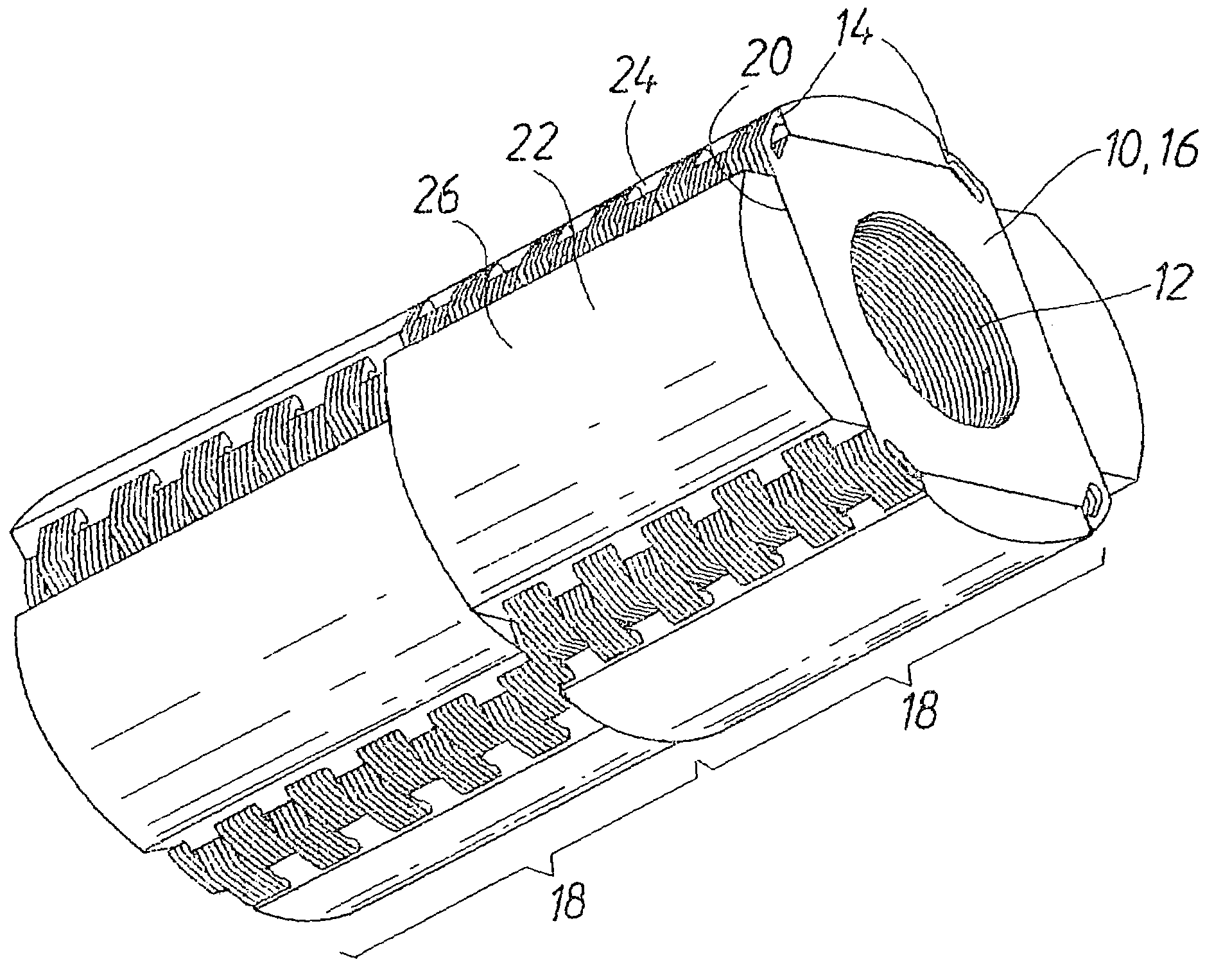
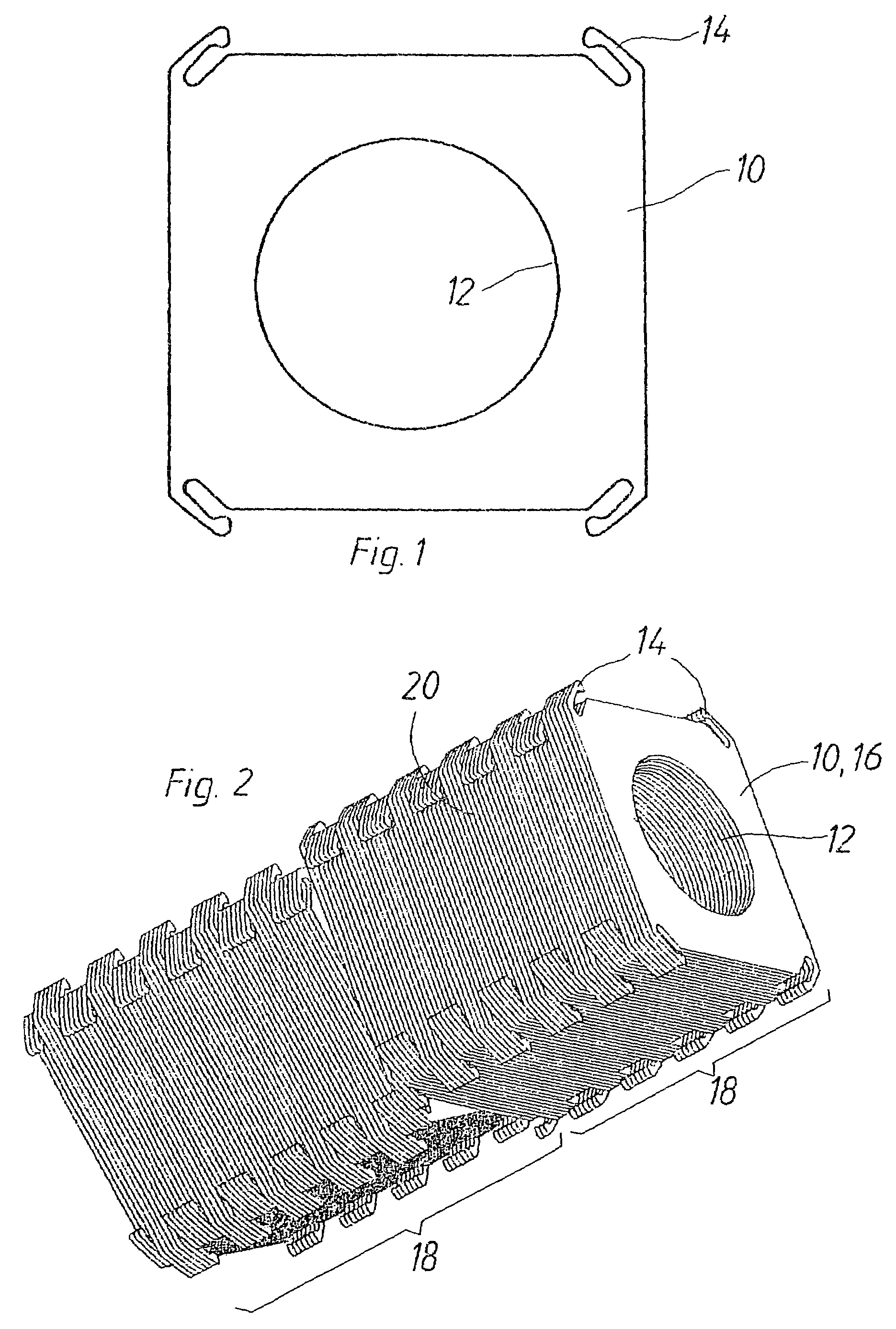
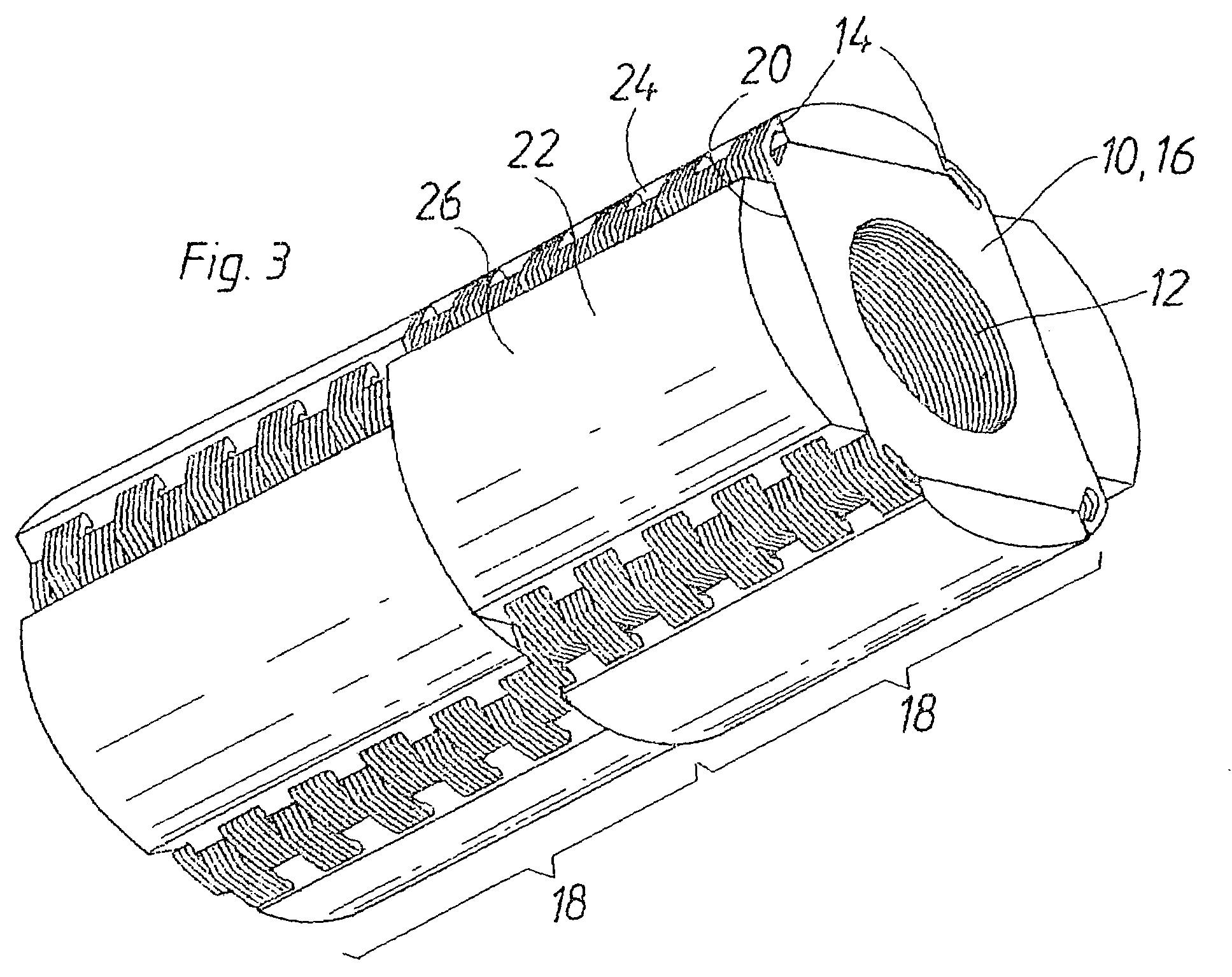
[0019]The lamination element or lamina 10 shown in FIG. 1 is stamped out of a metal sheet and has a substantially square shape with a center hole 12. On each corner, the lamination element 10 has a spring element 14, which is embodied as a spring tongue that is integral with the lamination element 10 and is produced in one operation along with the stamping out of the lamination element 10. Instead of being stamped, the lamination element 10 can also be produced with the spring elements 14 by laser cutting, water-jet cutting, erosion, or some other method. Two adjacent spring elements 14 each face toward one another and are associated with one another and form one pair of spring elements 14. In FIG. 1, the two upper and the two lower spring elements 14 are associated with one another respectively and form a pair.

[0020]For producing a short-circuit element 16, shown in FIG. 2, of a rotor of the invention, lamination elements 10 are assembled into a lamination packet 18. All the lamina...


PUM


Abstract

A rotor for an electric motor having a short-circuit element that has lamination packets in which the laminations of the short-circuit element are embodied with spring elements which press from two sides against permanent magnets of the rotor and as a result center the permanent magnets in the lateral direction independently of production tolerances. After the insertion of the permanent magnets between the spring elements, the short-circuit element with the permanent magnets is potted, for instance with synthetic resin, or spray-coated with plastic. The rotor has the advantage that it compensates for production tolerances of the permanent magnets.

Description

CROSS-REFERENCE TO RELATED APPLICATIONS[0001]This application is a 35 USC 371 application of PCT / DE 02 / 04629 filed on Dec. 18, 2002.BACKGROUND OF THE INVENTION[0002]1. Field of the Invention[0003]The invention relates to an improved rotor for an electrical machine, in particular for an electric motor.[0004]2. Description of the Prior Art[0005]It is known for rotors, for instance for brushless DC motors (BLDC motors), to be embodied with short-circuit element, on whose circumference permanent magnets are disposed. The short-circuit element can be assembled as a lamination packet made of laminations. For fastening purposes, it is known to glue the permanent magnets to the short-circuit element or to pot the short-circuit element and the permanent magnets with a synthetic resin or spray-coat them with plastic. Potting with synthetic resin is a kind of adhesive bonding. It is also known to insert the short-circuit element with the permanent magnets into a guard tube. A common feature of...

Claims


Application Information

Patent Timeline
Patent Type & Authority Patents(United States)
IPC IPC(8): H02K21/12H02K1/27
CPCH02K1/278
Inventor KOENIG, TILO
Owner ROBERT BOSCH GMBH
Why Eureka
Try Eureka