Phase locked loop circuit with a tunable oscillator and an independent frequency converter and frequency counter

a phase lock circuit and phase lock technology, applied in the direction of pulse technique, oscillation generator, modulation, etc., can solve the problems of reducing the frequency resolution, increasing the sensitivity of the pll to noise and sidetones, and already reducing the vco frequency at the phase detector

Inactive Publication Date: 2006-12-26
INTEL CORP
View PDF19 Cites 22 Cited by
  • Summary
  • Abstract
  • Description
  • Claims
  • Application Information

AI Technical Summary

Benefits of technology

[0020]The present invention is directed to a phase regulating arrangement of the generic type in such a manner that it meets high demands imposed on the phase noise, can be implemented with little effort and can be used in mobile radios.
[0023]This exemplary feature makes it possible to design the step-down frequency converter to be programmable, while the frequency counter is designed to be readable.
[0026]In addition, the step-down frequency converter may be in the form of a so-called multi-modulus divider or at least in the form of a dual-modulus divider so that, on average over time, a fractional rational divider ratio can be set at the step-down frequency converter. This advantageously makes it possible to operate the phase regulating arrangement described as a ΣΔ fractional N synthesizer.
[0027]The tunable oscillator and the frequency counter (which is designed to be readable) are, in one example, integrated on the same chip. This makes it possible to use the readable frequency counter to detect the frequency of the oscillator at the output thereof in a particularly precise manner. The readable frequency counter is used in such example to evaluate each edge of the oscillator output signal.
[0030]Asynchronous binary counters can advantageously be constructed in a simple manner, for example using flip-flop chains. Asynchronous counters can also be easily implemented for high frequencies. The propagation times within the counter can be taken into account without any problems when reading out the count.
[0033]It is advantageous to use a binary counter to measure the frequency since, in this case, the counter reading is in the same format as the desired value. The desired frequency of a PLL is usually represented as a binary word in multiples of the reference frequency, as a fractional multiple in the case of fractional N PLLs. Asynchronous counters can also be easily implemented for high frequencies but in such instances any propagation times which may be present in the counter should be taken into consideration during the reading-out operation.

Problems solved by technology

This may, of course, be ensured with a sufficiently large KV, that is to say with a steep slope, but has the disadvantage that it increases the sensitivity of the PLL to noise and sidetones.
This is problematic, in particular, in large scale integrated circuits since interference from other circuit blocks may be coupled over into the VCO via common supply voltages and a common substrate.
On the one hand, this is associated with the disadvantage that the VCO frequency at the phase detector has already been reduced by the divider factor n of the frequency divider, as a result of which the frequency resolution has been reduced or the measurement time required has been increased.
In addition, the circuit is not suitable as a frequency synthesizer that meets high demands in terms of the phase noise, as are required, however, for mobile radio systems such as GMS (Global System for Mobile Communication) or UTMS (Universal Mobile Telecommunication System).

Method used


Image

  • Phase locked loop circuit with a tunable oscillator and an independent frequency converter and frequency counter
  • Phase locked loop circuit with a tunable oscillator and an independent frequency converter and frequency counter
  • Phase locked loop circuit with a tunable oscillator and an independent frequency converter and frequency counter

Examples


Embodiment Construction

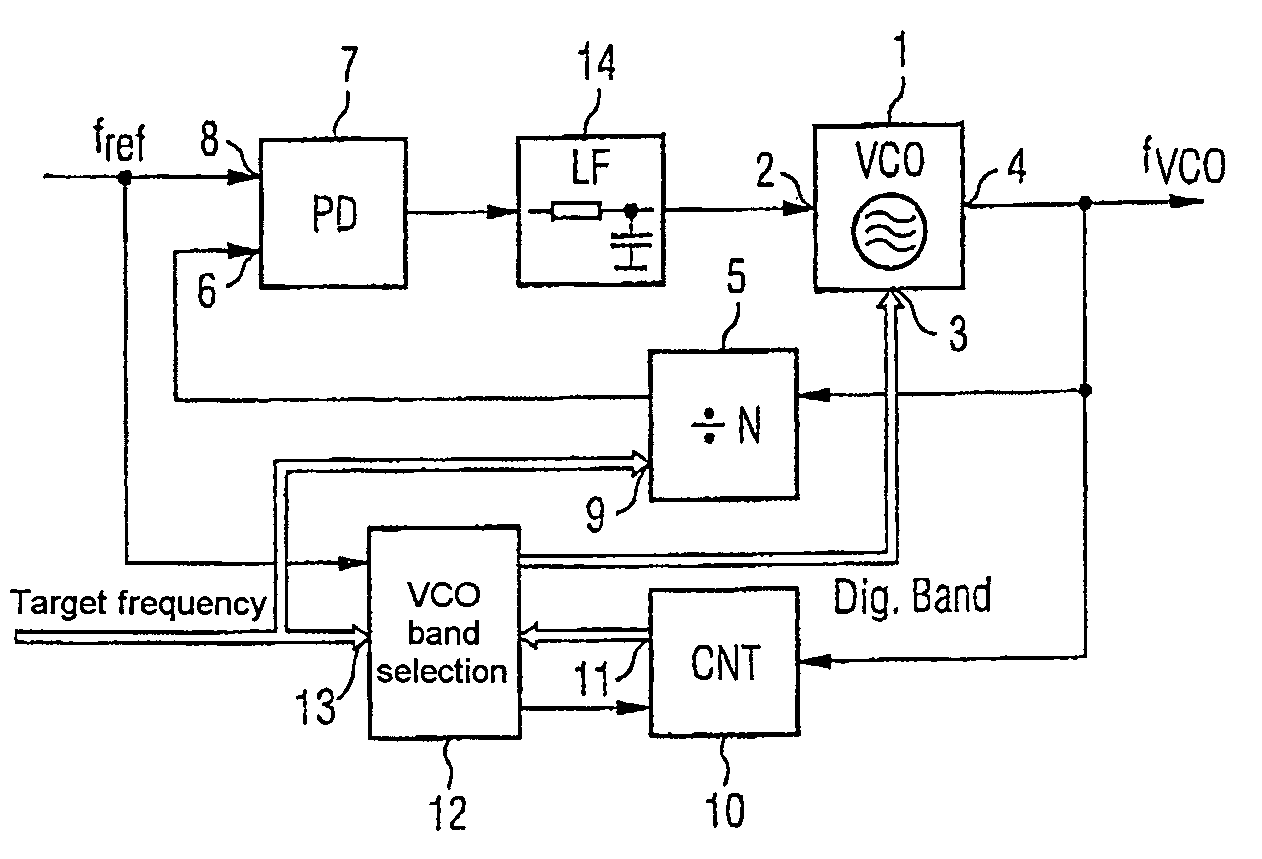
[0041]FIG. 1 shows a phase regulating arrangement, which is in the form of a PLL (Phase-Locked Loop) and has a tunable oscillator 1 having a plurality of frequency bands which can each be tuned. The tunable oscillator 1 has a tuning input 2, a selection input 3 for selecting a frequency band in a manner dependent on a control signal and an output 4, at which a signal at the desired oscillator frequency fVCO can be tapped off. The output 4 of the oscillator simultaneously forms the output of the phase regulating arrangement. The output 4 of the oscillator is connected to an input 6 of a phase detector 7 via a programmable frequency divider 5, which down-converts the frequency. A reference signal at a reference frequency fref is supplied to a further input 8 of the phase detector 7. In order to set the oscillator frequency fVCO, the frequency divider 5 has a programming input 9, to which the target frequency or an item of information derived from the target frequency is supplied in th...


PUM


Abstract

A phase regulating arrangement or circuit is disclosed, in which, in addition to a frequency divider, which is arranged in the feedback path of the PLL and, provision is made of a further frequency counter. The frequency counter is configured to be readable and is likewise connected to the oscillator output. The frequency counter drives a control unit that selects a desired frequency band of a multiband oscillator. The phase regulating arrangement or circuit described enables very fast settling in conjunction with low phase noise and good integration possibilities.

Description

REFERENCE TO RELATED APPLICATIONS[0001]This application is a continuation of PCT / DE2004 / 000304 filed Feb. 18, 2004 which was not published in English, that claims the benefit of the priority date of German Patent Application No. DE 103 08 643.9, filed on Feb. 27, 2003, the contents of which both are herein incorporated by reference in their entireties.FIELD OF THE INVENTION[0002]The present invention relates to a phase regulating arrangement.BACKGROUND OF THE INVENTION[0003]A phase regulating arrangement of the generic type is shown, for example, in the document U.S. Pat. No. 5,648,744. Said document shows an oscillator having a plurality of frequency bands which can be enabled and disabled and can each be tuned. In this case, the subband is selected by measuring the voltage at the loop filter, that is to say at the input of the oscillator and at the output of the phase detector, and increasing or decreasing the frequency band if certain limits are undershot or overshot.[0004]Phase ...

Claims


Application Information

Patent Timeline
Patent Type & Authority Patents(United States)
IPC IPC(8): H03L7/06H03L7/099H03L7/18H03K21/12H03K23/66H03K23/68H03L7/10H03L7/187H03L7/197
CPCH03K21/12H03K23/662H03K23/68H03L7/099H03L7/10H03L7/187H03L7/1974H03L7/1072
Inventor MUNKER, CHRISTIANSCHOLZ, MARKUS
Owner INTEL CORP
Why Eureka
Try Eureka