Micromechanical flow sensor with tensile coating

a micromechanical and flow sensor technology, applied in the field of sensors, can solve problems such as change or degradation of the function of these components, and achieve the effect of preventing buckling of the membran

Inactive Publication Date: 2006-12-26
SENSIRION HLDG
View PDF14 Cites 34 Cited by
  • Summary
  • Abstract
  • Description
  • Claims
  • Application Information

AI Technical Summary

Benefits of technology

[0006]Hence, it is an object to provide a sensor of the type mentioned initially that avoids this problem.

Problems solved by technology

As it has been found, the coating can otherwise lead to a change or degradation of the function of these components because it affects the electronic parameters of the semiconductor.

Method used


Image

  • Micromechanical flow sensor with tensile coating
  • Micromechanical flow sensor with tensile coating
  • Micromechanical flow sensor with tensile coating

Examples


Embodiment Construction

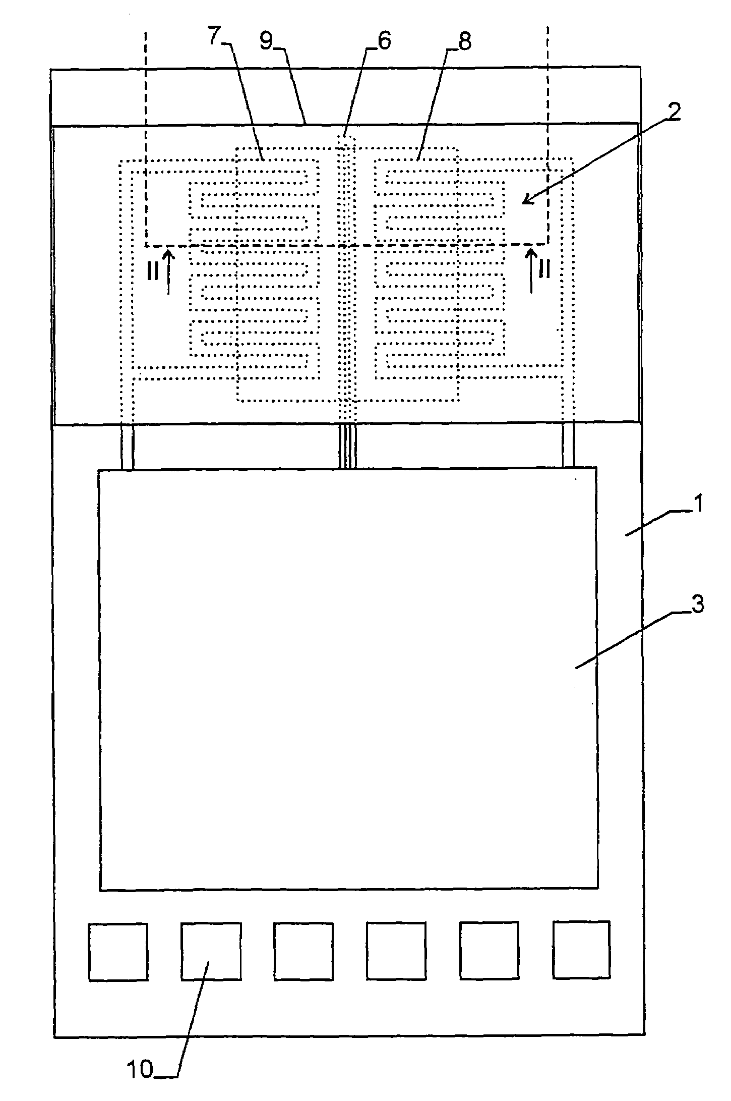
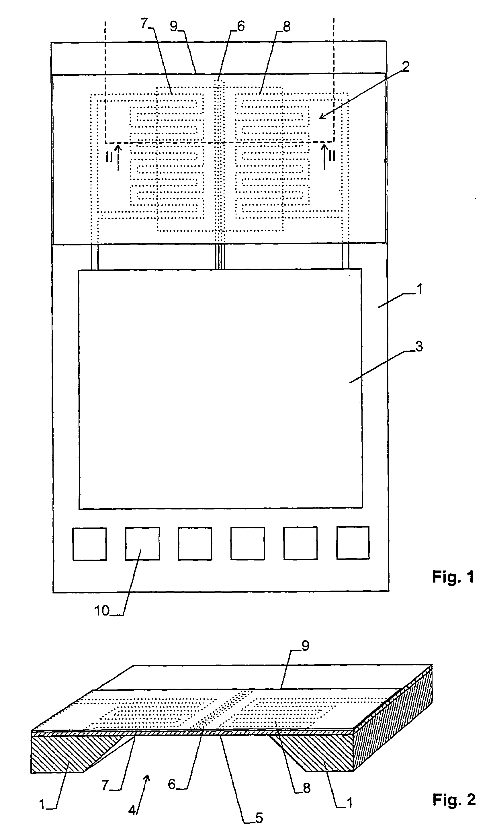
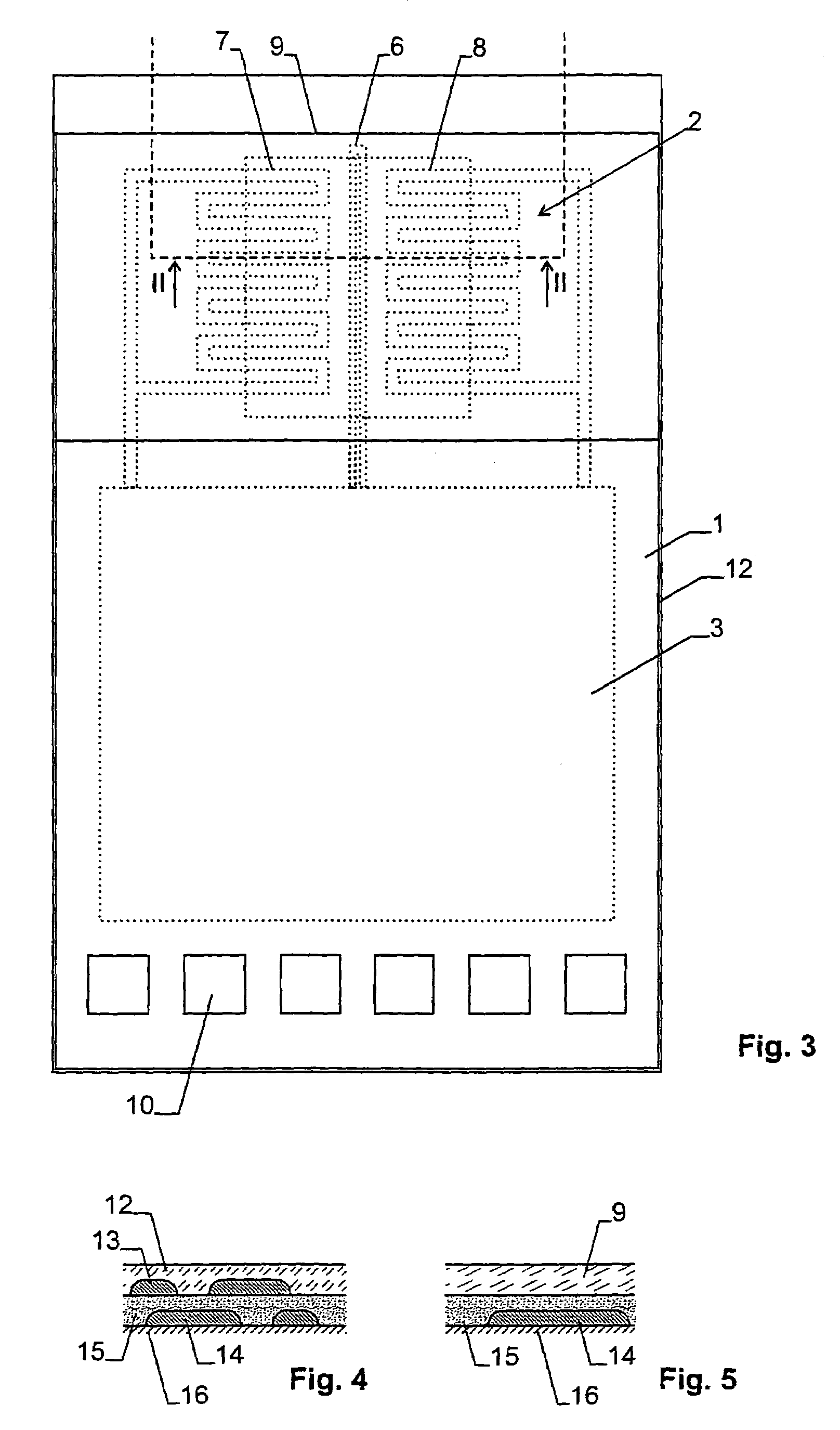
[0016]In FIGS. 1 and 2 an embodiment of the invention in the form of a flow sensor is shown. It comprises a semi-conductor device 1, onto which a measuring element 2 and a circuit 3 are integrated.

[0017]In semiconductor device 1 an opening or recess 4 has been etched out, which is covered by a thin membrane 5.

[0018]A heating 6 is arranged on membrane 5. Two meandering thermopiles 7, 8 are provided symmetrically to heating 6, which act as temperature sensors. The orientation of the thermopiles 7, 8 and the heating 6 in respect to the flow direction of the medium to be measured is such that the medium first flows over first thermopile 7, then over heating 6, and finally over second thermopile 8.

[0019]The measuring element 2 is covered by a tensile coating 9, which is under tensile stress and extends beyond membrane 5 on all sides or at least on two opposite sides of recess or opening 4. The overlap reaches at least sufficiently far in order to provide anchoring for the tensile coating...


PUM


Abstract

A sensor integrated on a semiconductor device (1), in particular a flow sensor, comprises a measuring element (2) on a membrane (5). In order to prevent a buckling of the membrane (5) a tensile coating (9) is applied. The coating covers the membrane, but it preferably leaves all the active electronic components integrated on the semiconductor chip (1) uncovered, such that their electrical properties are not affected.

Description

CROSS REFERENCE TO RELATED APPLICATIONS[0001]This application claims the priority of Swiss patent application 0031 / 01, filed Jan. 10, 2001, the disclosure of which is incorporated herein by reference in its entirety.BACKGROUND OF THE INVENTION[0002]The invention relates to a sensor as well as to a method of its production.[0003]Sensors of this type are e.g. flow or temperature sensors, where at least a part of the measuring element is arranged on a membrane. This membrane has often a thickness of a few micrometers only and spans an opening or recess in the semiconductor device.[0004]Preferably, further active electronic components are integrated on the semiconductor device of sensors of this type, such as transistors for amplifiers or reference voltage sources.[0005]The membrane is usually formed by the layers deposited during the production of the circuit, wherein the semiconductor below the layers is etched away. The layers that are deposited in most of the conventional production...

Claims


Application Information

Patent Timeline
Patent Type & Authority Patents(United States)
IPC IPC(8): H01C10/10G01F1/692B81B3/00G01F1/684G01F15/10H01L29/84
CPCG01F1/6845G01F15/10
Inventor VANHA, RALPH STEINERCLIENTO, TOMMASO FRANCESCO
Owner SENSIRION HLDG
Why Eureka
Try Eureka