Head support structure

a support structure and head technology, applied in the direction of maintaining the head carrier alignment, the alignment of track following on tapes, instruments, etc., can solve the problems of inability to adopt both-side support structures, inability to accurately reproduce, and inability to accurately record, so as to achieve effective suppression of oscillations at the free end of the support arm, reduce the number of components, and improve the effect of rigidity

Active Publication Date: 2006-12-26
FUJIFILM HLDG CORP +1
View PDF4 Cites 0 Cited by
  • Summary
  • Abstract
  • Description
  • Claims
  • Application Information

AI Technical Summary

Benefits of technology

[0020]Accordingly, a position displacement of the servo signals is suppressed at minimum in recording / reproduction, and thereby an effect is obtained that the recording / reproducing of highly accurate servo signals can be realized.
[0022]In accordance with the second aspect of the present invention the opposing distance between the base portion and the support arm can be adjusted by adjusting the support portion, and thereby a head position for a magnetic tape can be adjusted to a more optimal position. Thus an accurate recording / reproduction of servo signals can be more surely performed.
[0024]In accordance with the third aspect of the present invention, because the support portion is configured of the support member provided from any one of the base portion and the free end of the support arm toward the other, the number of components can be lessened and an advantage can be obtained that the free end of the support arm can be surely supported notwithstanding a less number of the components. In addition, rigidity can be heightened according to the less number of the components, and oscillations at the free end of the support arm can be effectively suppressed.

Problems solved by technology

In the conventional servo writer, because the support arm 52 is designed to be a one-side support structure, there is a problem that the oscillations are easy to transmit to the servo write head 50, it oscillates in lateral directions (X directions in FIG. 6) of the magnetic tape MT, and thus an accurate recording is difficult to be performed.
In addition, there is similarly a problem that an accurate reproducing is also difficult to be performed in reproduction.
Therefore, the both-side support structure cannot be adopted.

Method used


Image

  • Head support structure
  • Head support structure
  • Head support structure

Examples


Embodiment Construction

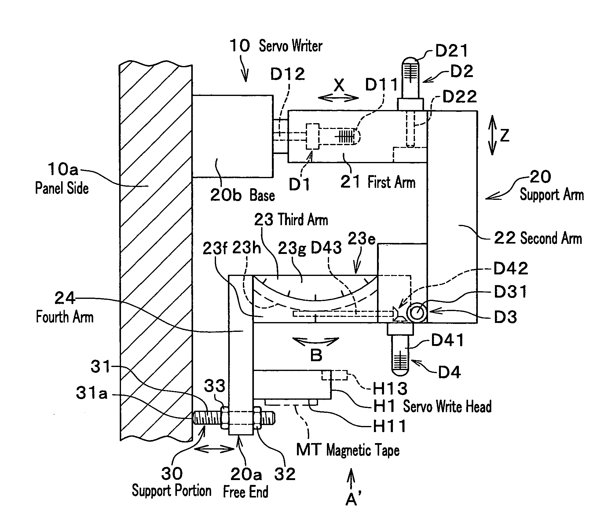
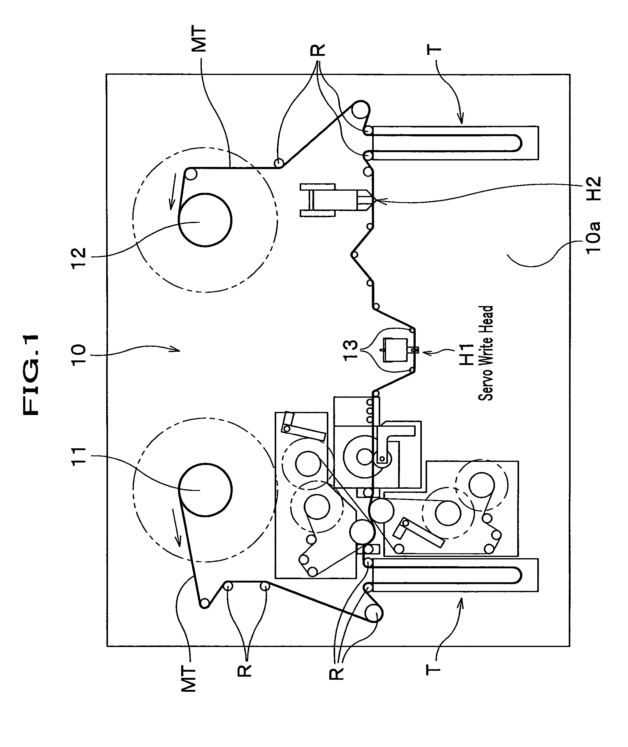
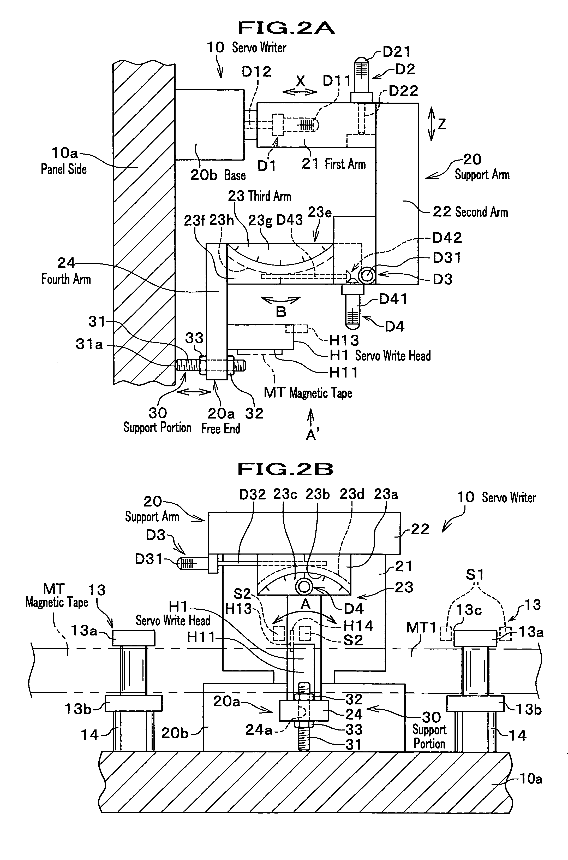
[0031]Here will be described a head support structure related to embodiments of the present invention in detail, referring to drawings. FIG. 1 is a configuration drawing conceptually showing one example of a servo writer for illustrating a head support structure related to an embodiment of the present invention. FIG. 2A is a schematic side view showing an overall configuration around a head; FIG. 2B is a schematic drawing viewed in an arrow mark A' direction in FIG. 2A. In addition, in the embodiment a support structure of a servo write head will be described.

[0032]At first an overall configuration of a servo writer 10 will be described. The servo writer 10 comprises a supply reel 11 for sending out a magnetic tape MT and a take-up reel 12 for winding the magnetic tape MT from the supply reel 11. At a downstream side of the supply reel 11 and an upstream side of the take-up reel 12 is arranged a servo write head H1 that writes, for example, servo signals with a bottom-open-reverse V...


PUM

PropertyMeasurementUnit
distanceaaaaaaaaaa
pushing forceaaaaaaaaaa
line densityaaaaaaaaaa

Abstract

A head support structure of the present invention is the head support structure for recording / reproducing a servo signal on a magnetic tape, comprises a base portion and a support arm, which is one-side supported at the base portion and provides a head provided position-adjustably at a free end for the magnetic tape, and provides a support portion for supporting the free end of the support arm for the base portion.

Description

BACKGROUND OF THE INVENTION[0001]1. Field of the Invention[0002]The present invention relates to a head support structure for recording / reproducing a servo signal on a tape-form recording medium (hereinafter referred to as magnetic tape).[0003]2. Description of the Related Art[0004]These years, in a magnetic tape used for a data backup and the like of a computer, an improvement of line density of further increasing the number of data tracks is intended in order to accurately read high-densely recorded data, and a technique of recording / reproducing servo signals on a plurality of servo bands neighboring these data tracks is adopted.[0005]In a magnetic tape system for using such servo signals, it is necessary to accurately write (record) the servo signals on the magnetic tape, and as an apparatus therefor, a servo writer is used.[0006]FIG. 6 is a drawing for illustrating a structure around a servo write head in a servo writer, and a servo write head 50 is attached to a free end 52a of...

Claims


Application Information

Patent Timeline
Patent Type & Authority Patents(United States)
IPC IPC(8): G11B5/584G11B21/24G11B5/49G11B5/56G11B15/60
CPCG11B5/584G11B15/60
Inventor KOMAI, HIROKAZU
Owner FUJIFILM HLDG CORP
Why Eureka
Try Eureka