
Wireless location determining device

a wireless location and wireless technology, applied in the field of wireless location determining devices, can solve the problems of consuming a considerable amount of power, affecting the accuracy of the positioning tag, and requiring substantial deployment time, so as to achieve the effect of improving the positioning accuracy of the tag

Active Publication Date: 2006-12-26
DAAK WIRELESS FUND
View PDF11 Cites 362 Cited by
  • Summary
  • Abstract
  • Description
  • Claims
  • Application Information

AI Technical Summary

Benefits of technology

[0043]The location accuracy of the tag may be refined by obtaining distance and / or direction information related to the relative position between the tag and the communication device, or by extrapolation, when the transmission of the unique data from the tag to the communication device and the determination of the location of the communication device are performed at different times.

Problems solved by technology

However, network-based methods for wireless location determination, require a dedicated infrastructure of antennas and transceivers, which is costly and takes substantial time to deploy.
However, handset-based wireless location devices are expensive, consume a considerable amount of power, are relatively big in size and radiate substantial RF power.
All the methods described above have not yet provided satisfactory solutions to the problem of wirelessly determining the location of small, inexpensive and low power roaming devices, over a wide area, without requiring a dedicated infrastructure.

Method used


Image

  • Wireless location determining device
  • Wireless location determining device
  • Wireless location determining device

Examples


Embodiment Construction

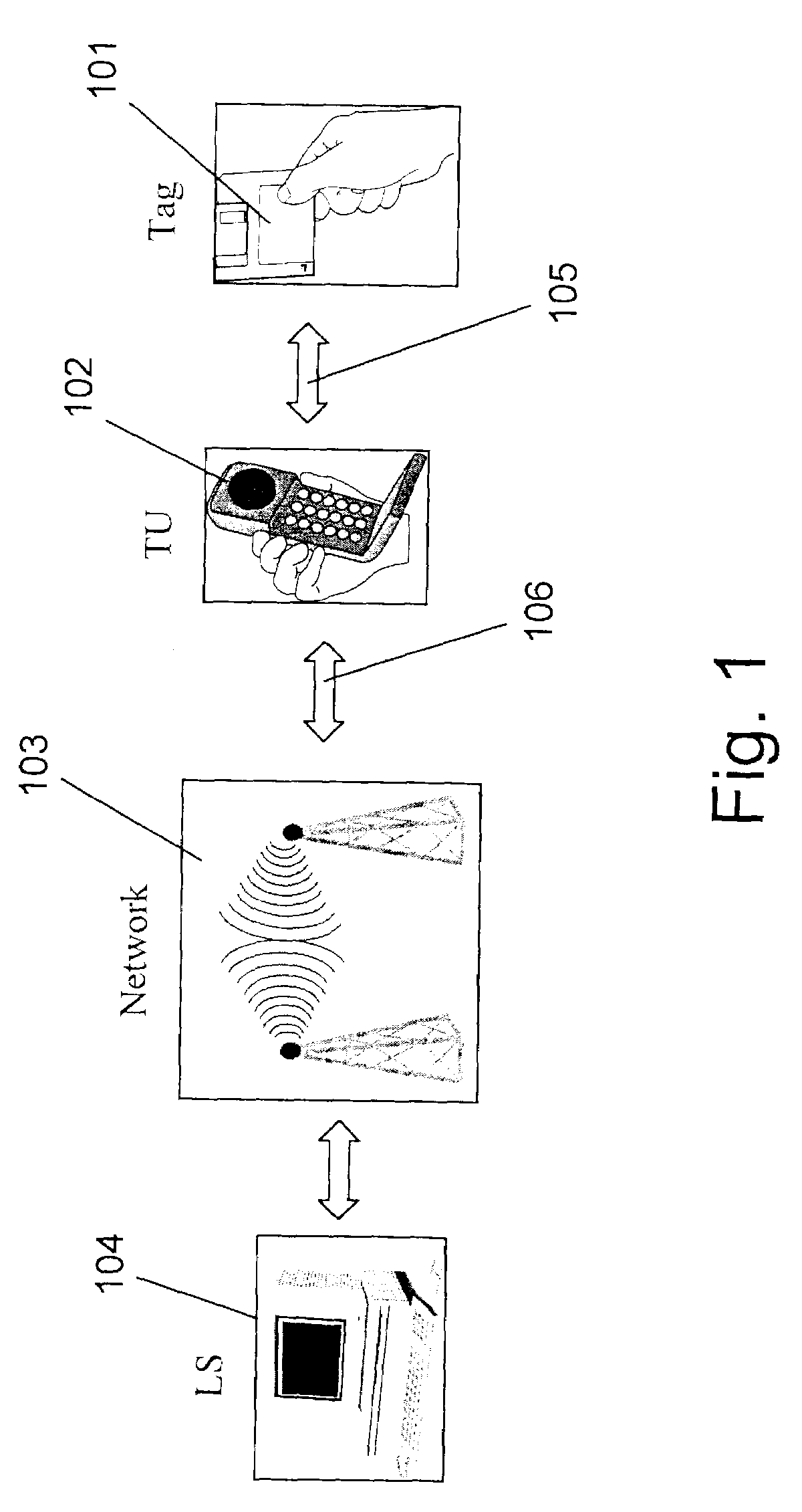
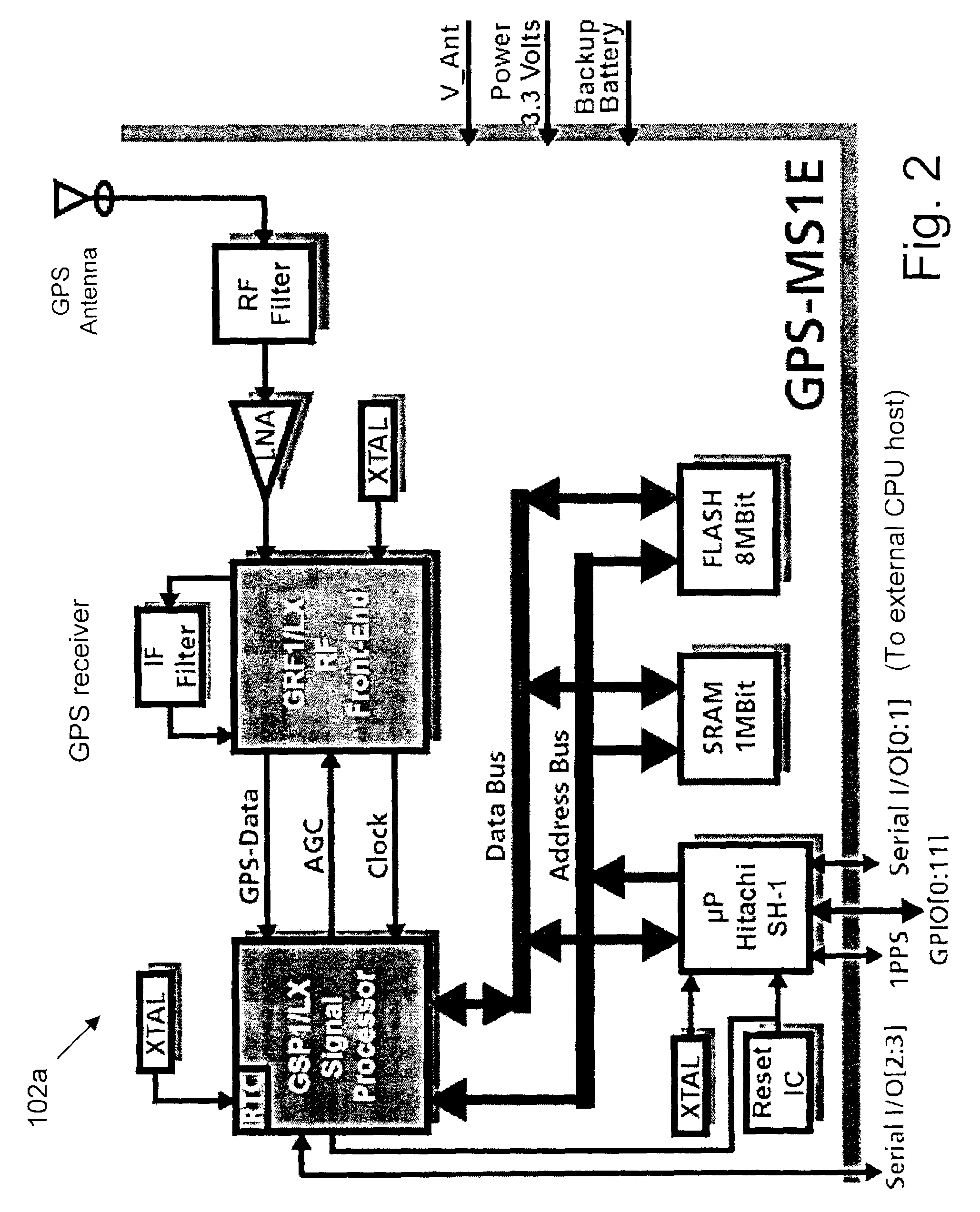
[0052]FIG. 1 is a block diagram of a system for determining the geographical location of roaming objects, in an area covered by a communication network (hereinafter referred to as “Telecom network”), according to a preferred embodiment of the invention. The system consists of at least one wireless tag 101, attached to a roaming object, in which a unique data is stored, a plurality of communication devices (hereinafter referred to as TUs, only one TU: 102 is shown), a wireless communication network 103 and a control center (i.e., LS: 104). Whenever required, the data stored in wireless tag 101 is transmitted to a destination (which may be, or may be linked to, control center 104),, trough TU 102 and over communication network 103. TU 102 and tag 101 obtain a short-range wireless transceiver (shown in FIG. 2), for communicating with each other. Preferably, communication network 103 is a cellular / mobile phone network and TU 102 is a cellular phone handset with an embedded GPS receiver ...


PUM


Abstract

The present invention discloses a system and a method to locate moving objects, such as people, pets and vehicles, over a wide area, by attaching small wireless devices, such as Bluetooth transceivers, to said objects and determining the location of said devices. The location of said wireless devices is determined by achieving ad-hoc short range wireless connectivity between said devices and communication devices such as Bluetooth enabled mobile phones that pass by, where said latter communication devices can be located by other means, such as GPS or network-based techniques.

Description

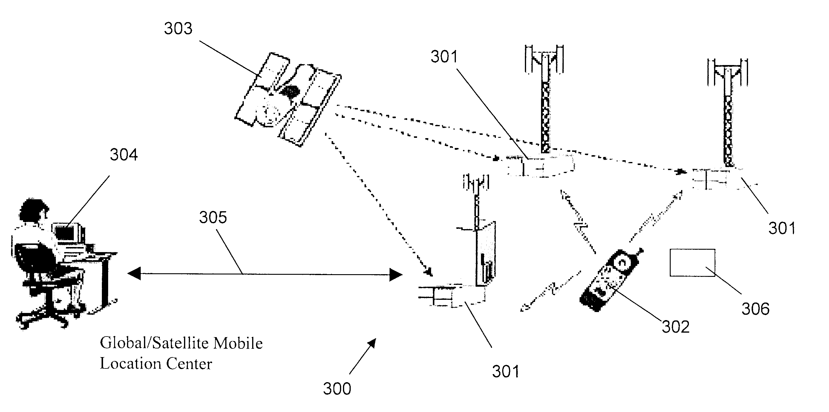
BACKGROUND OF INVENTION[0001]Moveable or roaming objects, including persons and animals, may be required, for various reasons, to be located by a third party or system, from a remote location. Examples for such needs may include persons in distress, particularly children, adults or handicapped people that require assistance, lost pets, stolen vehicles to be restored and transported assets to be tracked on their way.[0002]A conventional technique for locating roaming objects from remote location(s), involves utilizing wireless devices that are attached to these objects, in advance, and a radio network capable of communicating with these wireless devices and transmitting signals from which their location may be interpreted by a remote receiver. The communication channels in such network may comprise wireless and wireline elements, and the components of the network / system may be terrestrial, extraterrestrial airborne and space-borne. In some cases, this wireless location network serves...

Claims


Application Information

Patent Timeline
Patent Type & Authority Patents(United States)
IPC IPC(8): H04Q7/20G01S19/17H04W64/00
CPCG01S5/0289G01S13/82H04W64/00
Inventor KATZ, DANIEL A.
Owner DAAK WIRELESS FUND
Learn More