
Transition flow treatment process and apparatus

Inactive Publication Date: 2007-01-02
TEL FSI
View PDF92 Cites 11 Cited by
  • Summary
  • Abstract
  • Description
  • Claims
  • Application Information

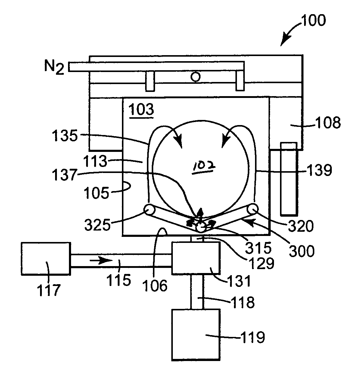
AI Technical Summary

Benefits of technology

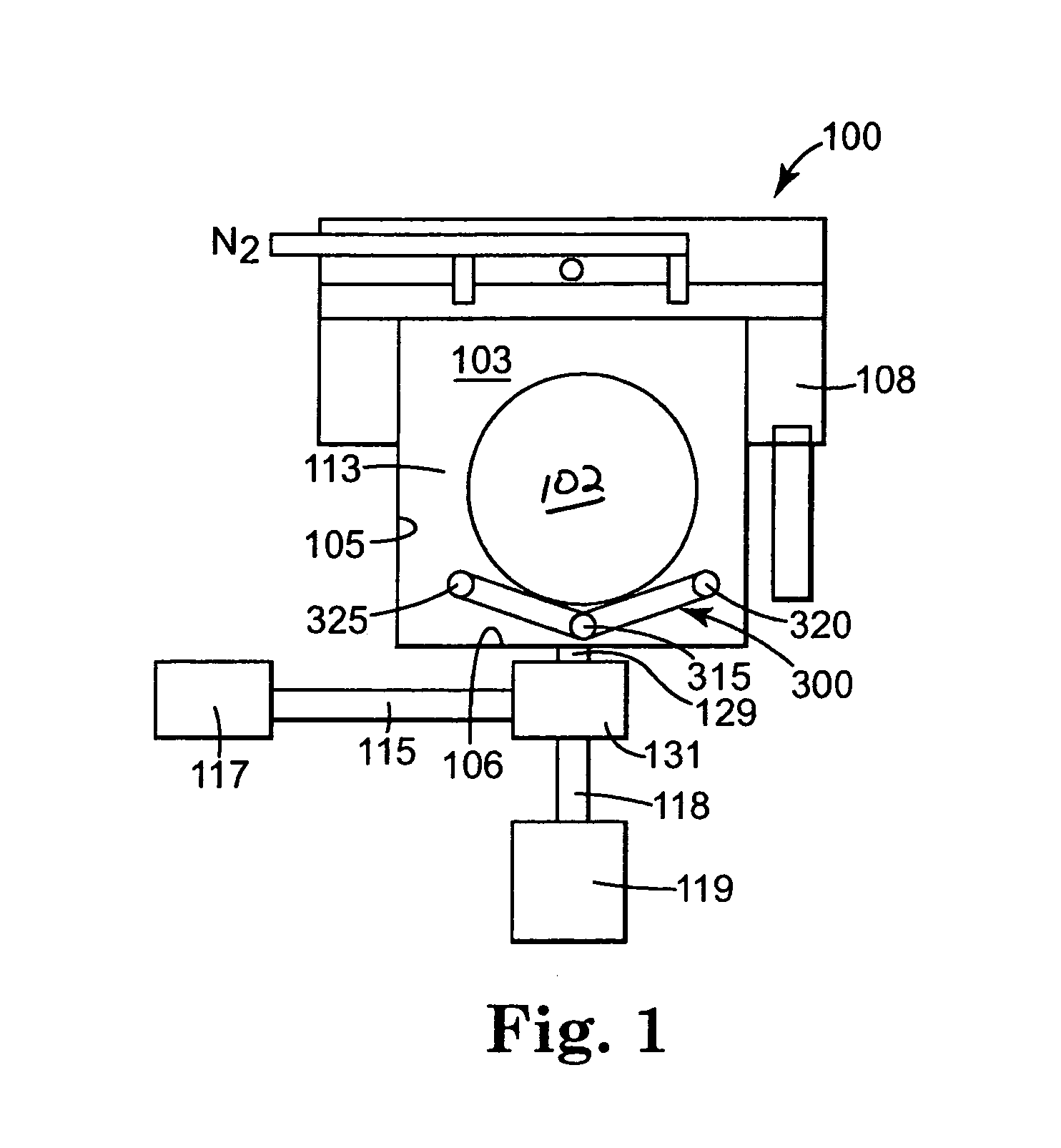
[0007]In practical effect, the present method causes a non-reactive bath to be first transitioned to a bath containing one or more treatment chemicals, and then transitioned back to a non-treating liquid bath. Preferably, the object(s) are immersed throughout the rinse-treat-rinse treatment. Material introduced to the bath is well-mixed with the bath contents so that, at a particular point in time, the chemical nature of the bath near the object(s) to be treated, and preferably throughout its volume, is as uniform as practically desired. Consequently, the substantial entirety of surfaces being treated tend to be exposed to a similar treatment. This results in substantial improvement in the uniformity of the treatment.
[0008]This “Transition-Flow” process is especially useful for carrying out etching treatments with excellent uniformity. While not being bound by theory, it is believed that the transitions of the environment of the object in the bath from a solution containing no treating chemical to substantially uniform increase in concentration of a treating chemical, followed by substantially uniform decrease in concentration of the treating chemical in the solution minimizes any differences in total treating effect at different locations on the object to be treated. In particular, it is believed that the effects of any slight spatial non-uniformities during the increase in concentration are diminished by similar, but opposite, non-uniformities during the decrease in concentration. In one aspect, one or more transitional chemical treatments all sandwiched between preferred rinsing treatments.
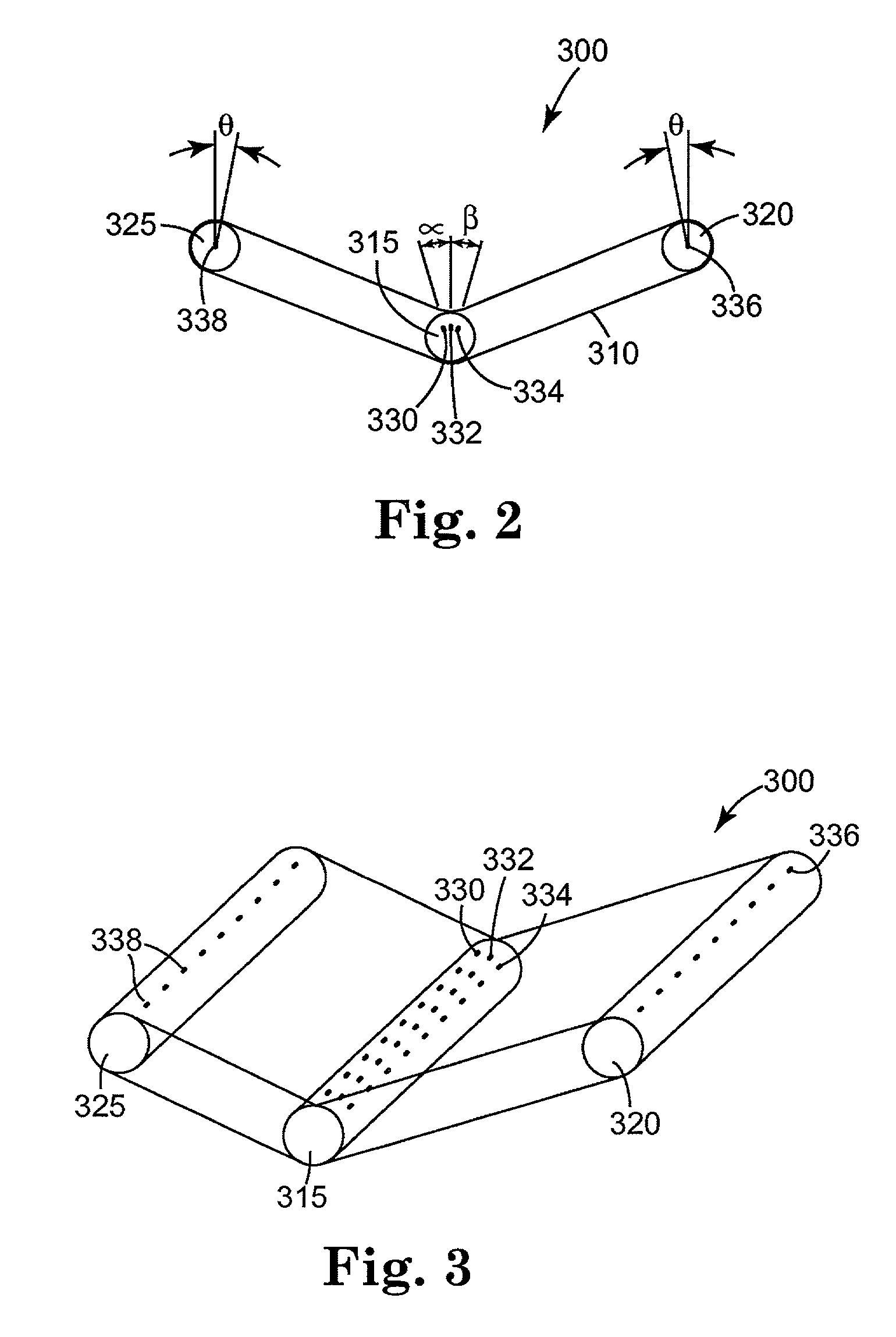
[0010]In the present invention, uniform changes in concentration are produced by introducing flow(s) of liquid and / or gas into the vessel with enough velocity and momentum such that eddy currents at least partially, and preferably substantially, envelop the object(s) being treated. These currents flow through the bath proximately to the object, producing a homogenous concentration of chemical(s) in the liquid through mixing. Eddy currents can be generated by any mixing mechanism, such as the use of spray orifices for introducing liquids (and / or gas as the case may be) in a mixing manner into the bath. Alternatively, pumps, impellers, bubblers, and the like may be used to provide a mixing action. The degree of mixing can be assessed by injecting dye into the liquid, and visually evaluating or by measuring through the use of quantitative analysis techniques the amount and flow of the dye at various locations of the liquid bath. A sodium salt of fluorescein dye is particularly effective in visualizing flow patterns in water.

Problems solved by technology

These objects have become increasingly more and more difficult to treat because they are being manufactured in smaller and smaller sizes, and contain extremely small features to be generated and treated.
This usually causes substantial mixing of the chemicals and the DI water.
The '158 patent states that mixing “causes the chemicals to be continuously diluted with water, which is undesirable since it is both environmentally preferable and cost effective to recycle the chemical solutions.
It has been observed that true plug-flow conditions are very difficult to achieve, resulting in heterogeneous treatment of wafers.
Thus, one portion of the wafer may be exposed to etchant for a longer period of time or at a different concentration than other portions of the wafer, causing a difference in performance of the wafer depending on the location of evaluation of the wafer.

Method used


Image

  • Transition flow treatment process and apparatus
  • Transition flow treatment process and apparatus
  • Transition flow treatment process and apparatus

Examples


example 1

Measuring the Uniformity of Chemical Concentration

[0073]For purposes of the present invention, the process of the present invention is carried out such that a uniform increase or decrease of concentration of the treating chemical is observed during each transition in bath content. This evaluation is preferably carried out proximally to the surface of the object to be treated. A solution is considered to be uniform in concentration if, at any given time in the process, the concentration of the treating chemical varies by no more than about 50%, and preferably no more than about 20% near the surface of the object to be treated. Areas of the bath far from the treated surfaces are not of interest and are not to be included in concentration measurements.

[0074]The concentration near the surface of an object to be treated can be determined by any appropriate technique, such as by measuring the conductivity of the liquid at representative locations in the liquid to be evaluated. In this ran...

example 2

Measuring the Uniformity of the Etch

[0077]In the case of etching, the amount of material removed by an etching process is measured at several points on the surface of the wafer. At least 9 to 121 sites are typical, with 49 or so measurements being preferred.

[0078]In the case of measuring the uniformity of the SiO2 etching process at 49 sites evenly distributed on a 300 mm diameter silicon wafer used in the production of semiconductor devices, the following procedure can be used. The initial thickness of the SiO2 is measured at each point on a Rudolph Caliber 300 ellipsometer, commercially available from Rudolph Research, or the equivalent, and the measured values stored in its on-board computer (the “pre” measurement). The wafer is then processed with a treating chemical (typically dilute HF) to etch away some of the SiO2, rinsed and dried. The thickness of SiO2 at the same 49 points on the wafer is then re-measured on the ellipsometer (the “post” measurement). The location of the 4...

example 3

Measuring of the Uniformity of a Transition Etch Compared to that of a Soak-Etch and an Etch in a Separate, Recirculated HF Bath

[0088]FIG. 14 shows the etch uniformity results of wafers processed in three ways:[0089]Comparison 3A: wafers etched by immersion in a separate, dedicated, recirculated bath of HF and transferred to a bath of flowing water for rinsing (dedicated-bath etch);[0090]Comparison 3B: wafers etched by immersion into a pre-mixed bath of HF and soaking, followed by an in-situ rinse in the same tank (soak etch); and[0091]Comparison 3C: wafers etched by immersion into flowing DI water followed by a transition-in to flowing HF followed by a transition-out to flowing DI water (Transition Etch of the present invention)

[0092]The wafers for the dedicated-bath treatment were immersed for 140 seconds in a 40 liter bath of 200:1 HF being recirculated at 40 lpm. The wafers were then robotically transferred to a 40 l rinse bath in an etch / rinse / dry tank which overflowed DI water...


PUM

PropertyMeasurementUnit
Fractionaaaaaaaaaa
Fractionaaaaaaaaaa
Lengthaaaaaaaaaa

Abstract

A method is provided for treating an object. In this method, a treating chemical is introduced to a bath under conditions effective to at least partially envelop the object to be treated in eddy currents of the bath liquid, followed by introducing non-treating liquid into the bath under conditions effective to at least partially envelop the object to be treated in eddy currents of the bath liquid. An apparatus for carrying out this method is also provided.This method is particularly beneficial for objects used in precision manufacturing by treatment with solutions, such as semiconductor wafers or similar substrates.

Description

FIELD OF THE INVENTION[0001]The present invention relates to the field of treating objects by a liquid such as for cleaning or otherwise treating one or more surfaces of the object. In particular, the present invention is directed to a method and apparatus for treating objects, such as a microelectronic substrate or other device, and in particular, for subjecting one or more surfaces of the object to a liquid for treating it.BACKGROUND OF THE INVENTION[0002]The present invention has been developed, in particular, for its application to objects that are treated with a solution, such as semiconductor wafers or similar substrates, whether raw, etched with any feature, coated, or integrated with conductor leads or traces as an integrated circuit device, lead frames, medical devices, disks and heads, flat panel displays, microelectronic masks, micromechanical devices, microoptical devices, and the like. These objects have become increasingly more and more difficult to treat because they ...

Claims


Application Information

Patent Timeline
IPC IPC(8): B08B3/00B08B3/08B08B3/10B08B3/04H01L21/00H01L21/027H01L21/304H01L21/306
CPCB08B3/102H01L21/02052H01L21/67057H01L21/6708H01L21/67051Y10S438/906H01L21/00B08B3/10H01L21/306
Inventor CHRISTENSON, KURT KARLLEE, NAM PYOMICHALKO, GARY WILLIAMRATHMAN, CHRISTINA ANN
Owner TEL FSI
Learn More