Transient compensation voltage estimation for feedforward sinusoidal brushless motor control

a brushless motor and compensation voltage technology, applied in the direction of electronic commutators, electric programme control, instruments, etc., can solve the problems of parasitic torque ripple components at various frequencies, deviations from pure sinusoidal back emf and current waveforms, and typical power requirements of electric power steering

Inactive Publication Date: 2007-01-02
STEERING SOLUTIONS IP HLDG +1
View PDF106 Cites 33 Cited by
  • Summary
  • Abstract
  • Description
  • Claims
  • Application Information

AI Technical Summary

Problems solved by technology

Therefore, electric power steering typically requires power only on demand.
However, due to practical limitations of motor design and controller implementation, there are always deviations from pure sinusoidal back EMF and current waveforms.
Such deviations usually result in parasitic torque ripple components at various frequencies and magnitudes

Method used


Image

  • Transient compensation voltage estimation for feedforward sinusoidal brushless motor control
  • Transient compensation voltage estimation for feedforward sinusoidal brushless motor control
  • Transient compensation voltage estimation for feedforward sinusoidal brushless motor control

Examples


Embodiment Construction

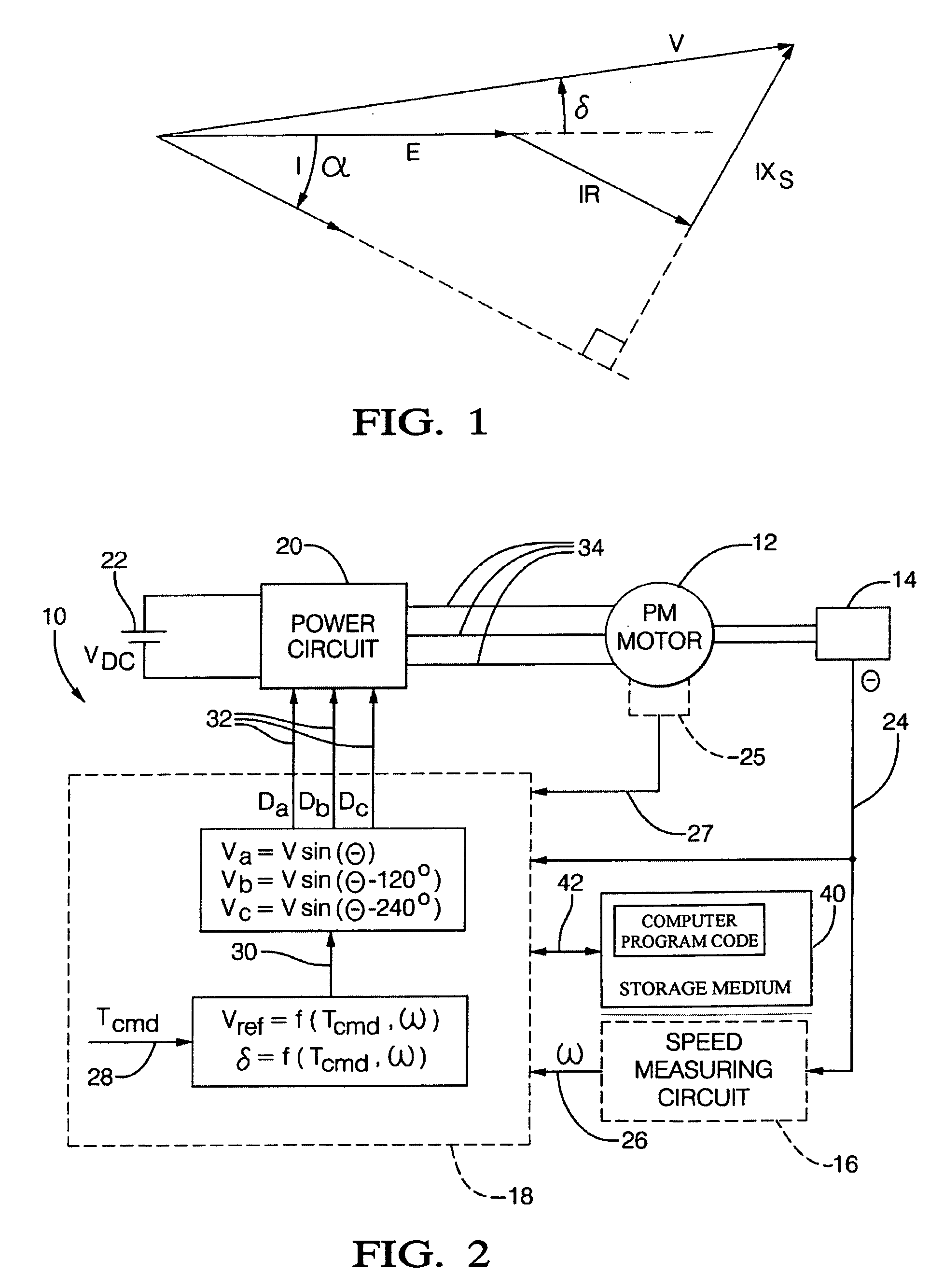
[0016]Referring now to the drawings in detail, FIG. 2 depicts a PM motor system 10 where numeral 10 generally indicates a system for controlling the torque of a sinusoidally excited PM electric machine 12 (e.g. a motor, hereinafter referred to as a motor). The system includes, but is not limited to, a motor rotor position encoder 14, a speed measuring circuit 16, a controller 18, power circuit or inverter 20 and power source 22. Controller 18 is configured to develop the necessary voltage(s) out of inverter 20 such that, when applied to the motor 12, the desired torque is generated. Because these voltages are related to the position and speed of the motor 12, the position and speed of the rotor are determined. A rotor position encoder 14 is connected to the motor 12 to detect the angular position of the rotor denoted θ. The encoder 14 may sense the rotary position based on optical detection, magnetic field variations, or other methodologies. Typical position sensors include potentio...


PUM


Abstract

A method for controlling a voltage mode controlled electric machine comprising: receiving a torque value representative of a desired torque; obtaining a speed value indicative of a rotational velocity of the electric machine; acquiring a phase advance value indicative of a desired phase advance angle; generating a voltage command responsive to the torque value, the position value; the generating is responsive to the torque value, the speed value, and the phase advance value.

Description

BACKGROUND[0001]Most modem vehicles have power steering in which the force exerted by the operator on the steering wheel is assisted by hydraulic pressure from an electric or engine-driven pump. The force applied to the steering wheel is multiplied by the mechanical advantage of a steering gear. In many vehicles, the steering gear is a rack and pinion, while in others it is a recirculating ball type.[0002]Electric power steering is commonly used in vehicles to improve fuel economy and has started to replace hydraulic power steering in some vehicles. One way this is accomplished is through the reduction or elimination of losses inherent in traditional steering systems. Therefore, electric power steering typically requires power only on demand. Commonly, in such systems an electronic controller is configured to require significantly less power under a small or no steering input condition. This dramatic decrease from conventional steering assist is the basis of the power and fuel savin...

Claims


Application Information

Patent Timeline
IPC IPC(8): G05B19/10B62D5/04H02P6/14H02P6/16
CPCB62D5/046H02P6/16H02P6/142G05B2219/42063H02P6/15
Inventor COLLIER-HALLMAN, STEVEN JAMES
Owner STEERING SOLUTIONS IP HLDG
Why Eureka
Try Eureka