System and method for varying exposure time for different parts of a field of view while acquiring an image

a technology of exposure time, applied in the field of system and method for varying exposure time for different parts of a field of view while acquiring an image, can solve the problems of difficult to obtain an bleeding or streaking into the immediate surrounding area, and the problem of obtaining a good image of a more faint object adjacent to a bright object still persists, so as to increase the resolution of masking the image

Active Publication Date: 2007-01-02
TEXAS INSTR INC
View PDF11 Cites 31 Cited by
  • Summary
  • Abstract
  • Description
  • Claims
  • Application Information

AI Technical Summary

Benefits of technology

[0010]In accordance with yet another aspect of the present invention, a device for masking one or more selected areas of a field of view while capturing an image, is provided. The device comprises: a first DMD, a second DMD, and a CCD. An image aperture is formed in the device. The first DMD comprises a first array of electrically controllable and movable mirror elements. The first DMD is positioned at a first angle with respect to a central axis of image light rays entering the device through the image aperture. Also, the first DMD is positioned so that the image light rays will hit at least some of the mirror elements on the first DMD. The second DMD comprises a second array of electrically controllable and movable mirror elements. The second DMD is positioned at a first spaced distance from the first DMD. The second array of mirror elements faces in an opposite direction than the first array of mirror elements. The second DMD is positioned so that, when at least some of the first DMD mirror elements are in a first position, at least some of the image light rays reflected from the first DMD mirror elements positioned in the first position

Problems solved by technology

In astrophotography, it is often difficult to obtain an image of a more faint object, such as a nebula, a spiral arm of a distant galaxy, or a distant star, when there is a closer and brighter star along an immediately adjacent line of sight.
The difficulty is that in trying to get a longer exposure time for the more faint object (e.g., to increase the signal-to-noise ratio), such longer exposure of the adjacent brighter star within the field of view often overexposes or saturates the area where the bright star is located and may cause bleeding or streaking into the immediate surrounding areas.
However, the problem of obtaining a good image of a more faint object adjacent to a bright object still persists.
Although binning may increase sensitivity, it does so at a sacrifice to resolution because binning effectively decreases the number of pixels per square inch.
As mentioned above, the problem that often arises with longer exposure times is saturation at areas within the field of view where a

Method used


Image

  • System and method for varying exposure time for different parts of a field of view while acquiring an image
  • System and method for varying exposure time for different parts of a field of view while acquiring an image
  • System and method for varying exposure time for different parts of a field of view while acquiring an image

Examples


first embodiment

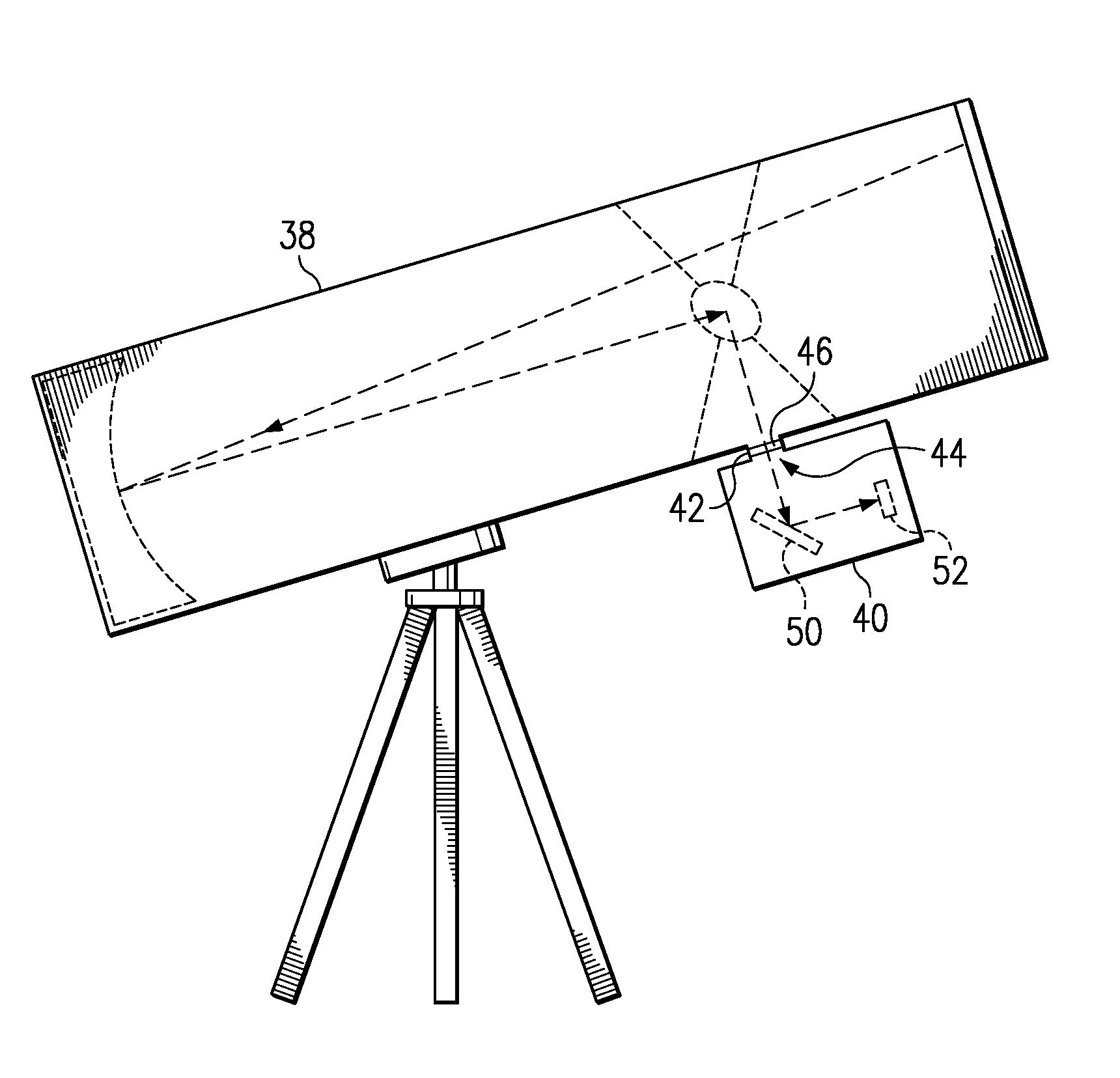
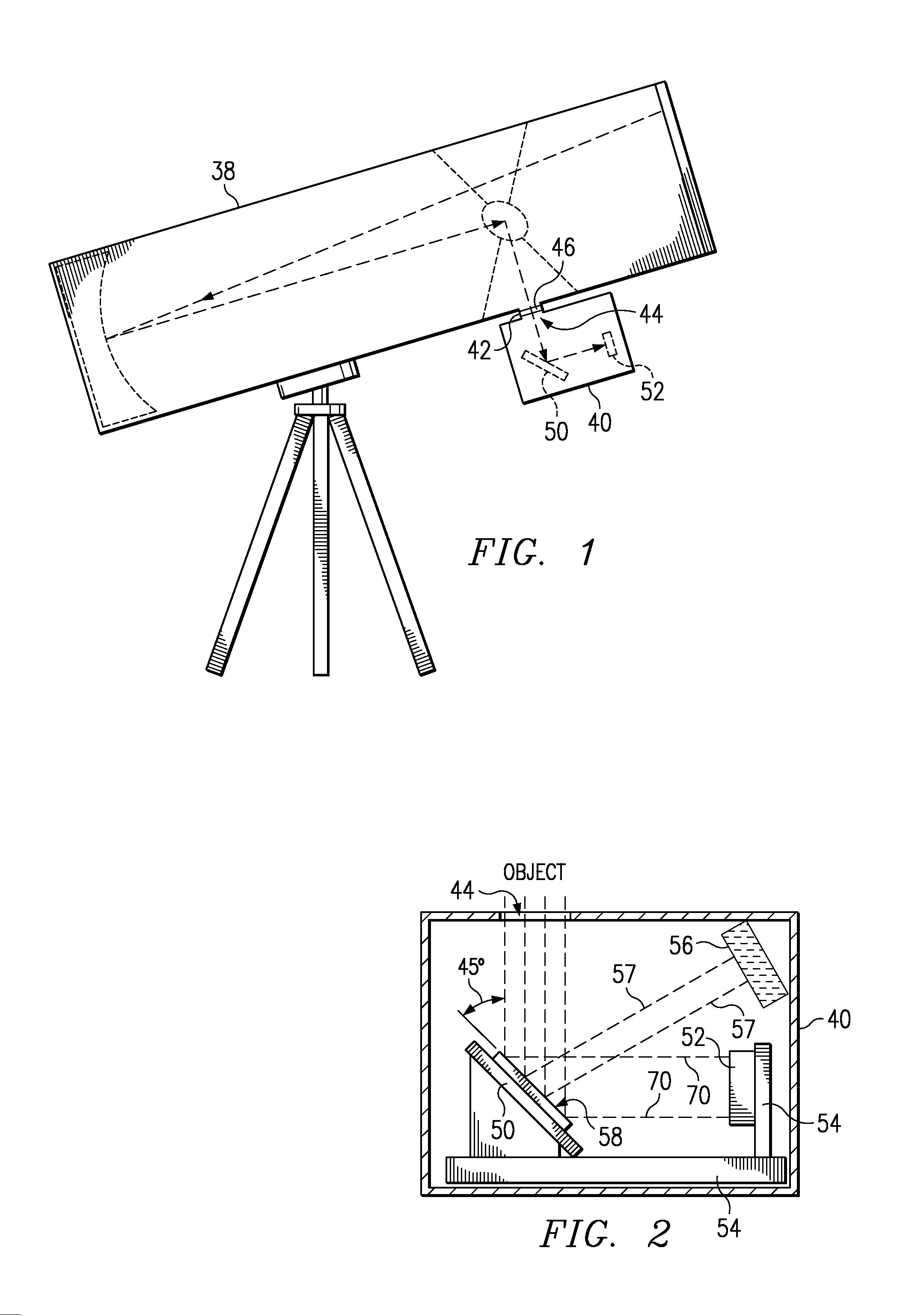
[0033]Referring to FIG. 2, the device 40 comprises a spatial light modulator (SLM) device 50 and an image capturing device 52. In the first embodiment, the SLM device 50 is a digital micro-mirror device (DMD) (DMDs are also sometimes known as a deformable mirror devices). There are many different types and designs of SLM devices, including but not limited to: DMDs, such as those developed by Texas Instruments, Inc.; anti-reflective membrane (AR membrane) devices, such as those developed by AT&T Bell Labs; and deformable film membrane devices, for example.

[0034]There are many different designs for DMDs that may be used in an embodiment of the present invention. Preferably, the DMD 50 can independently actuate mirror elements between a first position and a second position. The DMD 50 may also have the capability to actuate the mirror elements to more than two positions or oscillate the mirror elements. The image capturing device 52 in the first embodiment is a CCD (charge-coupled devi...

second embodiment

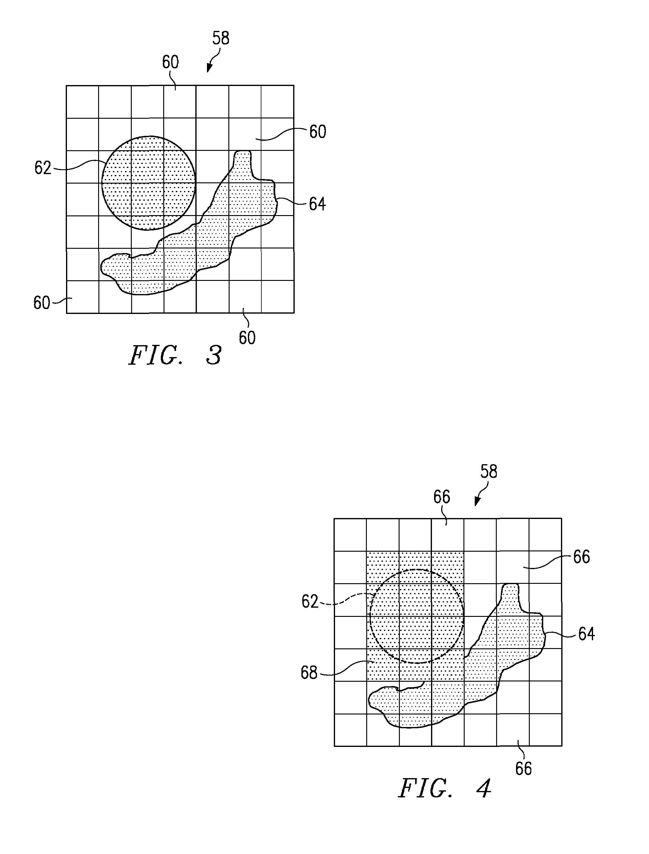
[0064]In the second embodiment, the first DMD 50 is identical to the second DMD 170, and both have an array of movable micro-mirror elements 60 on their faces 58, 174. However in other embodiments, the first and second DMDs 50, 170 may not be identical. FIG. 18 shows the face 174 of the second DMD 170 superimposed onto the face 58 of the first DMD 50, as aligned by the image rays and as would be seen from the CCD 52. In FIG. 18, the shaded squares 176 represent the mirror elements on the first DMD face 58 that are tilted to a second position to mask the portions of the image 172 striking the mirror elements 176 tilted to the second position (see reflections of image light rays 172 in FIG. 16). In FIG. 19, the darker shaded squares 178 represent the mirror elements on the second DMD face 174 that are tilted to a second position to mask the portions of the image 173 reflected from the first DMD 50 that strike the mirror elements 178 tilted to the second position (see reflections of im...

third embodiment

[0066]FIG. 20 shows a device 40 in accordance with the present invention, in which the device 40 uses three DMDs 50, 170, 180 and one CCD 52. The second DMD 170 is shifted relative to the first DMD 50, and the third DMD 180 is shifted relative to the second DMD 170. Thus, the resolution may be further enhanced by adding the third DMD 180. FIGS. 21–23 illustrate the faces 58, 174, 182 of the three DMD elements 50, 170, 180, respectively, of FIG. 20 superimposed upon each other, as aligned by the image rays and as seen from the CCD. Although not shown, other embodiments may have four, five, or more DMDs to still further increase the resolution. However, at some point the expense of multiple DMDs and / or the increase in complexity of the device 40 versus the benefit, will likely create a practical limit to the number of desired DMDs to be used in a device 40.

[0067]The present invention also may be incorporated in other embodiments for use in a variety of other ways outside the field of ...


PUM


Abstract

A system and method for exposing different parts of a single field of view for various and differing lengths of time while capturing an image is provided. For astrophotography, unwanted light pollution or over-saturation bleeding from nearby or obtrusive stars may be greatly reduced or eliminated while still capturing the image of the nearby brighter star in the same field of view. Also, a system and method for real-time contrast control while capturing an image to optimize signal-to-noise ratio for various parts of the captured image, is provided. An embodiment of the present invention provides such techniques by using spatial light modulator devices, such as a digital micro-mirror device, to controllably mask different portions of light from an image that expose film or a charge-coupled device. A system and method for a way to use a spatial light modulator device as an active and controllable mask for photolithography, is provided.

Description

FIELD OF THE INVENTION[0001]The present invention relates to a system and method for varying exposure time for different parts of a field of view while acquiring an image.BACKGROUND[0002]In astrophotography, it is often difficult to obtain an image of a more faint object, such as a nebula, a spiral arm of a distant galaxy, or a distant star, when there is a closer and brighter star along an immediately adjacent line of sight. The difficulty is that in trying to get a longer exposure time for the more faint object (e.g., to increase the signal-to-noise ratio), such longer exposure of the adjacent brighter star within the field of view often overexposes or saturates the area where the bright star is located and may cause bleeding or streaking into the immediate surrounding areas.[0003]The recent use of digital image sensors, such as a charge coupled device (CCD), as well as the recent improvements in increased resolution (more pixels or sensors per square inch) and increased sensitivi...

Claims


Application Information

Patent Timeline
IPC IPC(8): H04N5/225G02B23/02G02F1/31H04N5/238
CPCG02B23/02H04N5/238H04N5/2254G02F1/31H04N23/55H04N23/75
Inventor NEIDRICH, JASON MICHAEL
Owner TEXAS INSTR INC
Why Eureka
Try Eureka