
Distributed and discrete amplification of optical signals

a technology of optical signals and distribution channels, applied in the field of communication systems, can solve the problems of inacceptable noise figure (nf) over the 100 nm gain bandwidth, high cost, and complicated implementation of amplifiers, etc., and achieve the effect of widening the gain bandwidth and reducing the noise figur

Inactive Publication Date: 2007-01-02
SPRINT CORPORATION
View PDF6 Cites 1 Cited by
  • Summary
  • Abstract
  • Description
  • Claims
  • Application Information

AI Technical Summary

Benefits of technology

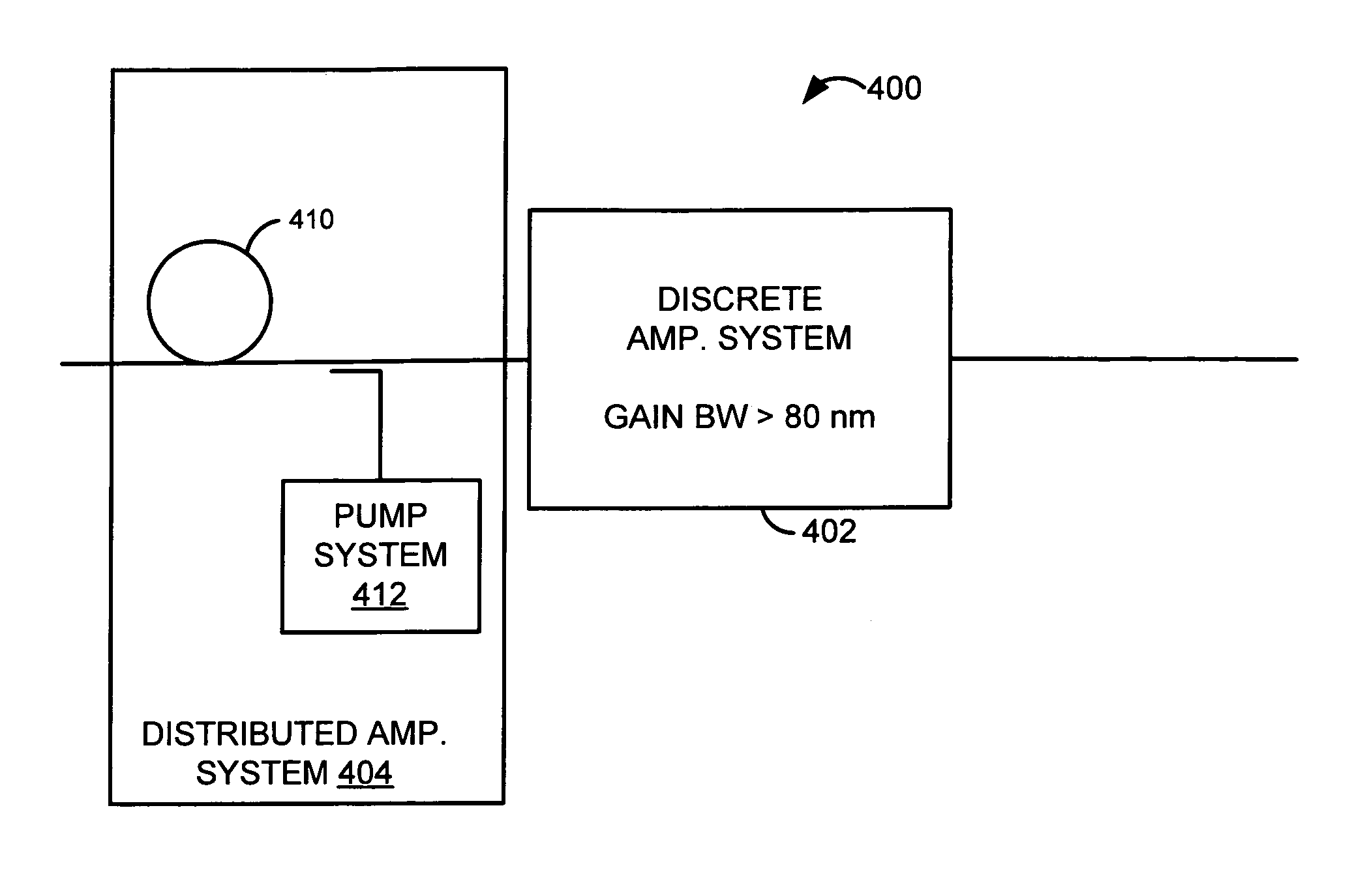
[0013]The optical amplifier system advantageously provides a wider gain bandwidth than traditional EDFAs and provides a lower and flatter noise figure than other wide-gain bandwidth configurations. By having a lower, flatter noise figure, the longer and shorter wavelength bands may carry data over long distances.

Problems solved by technology

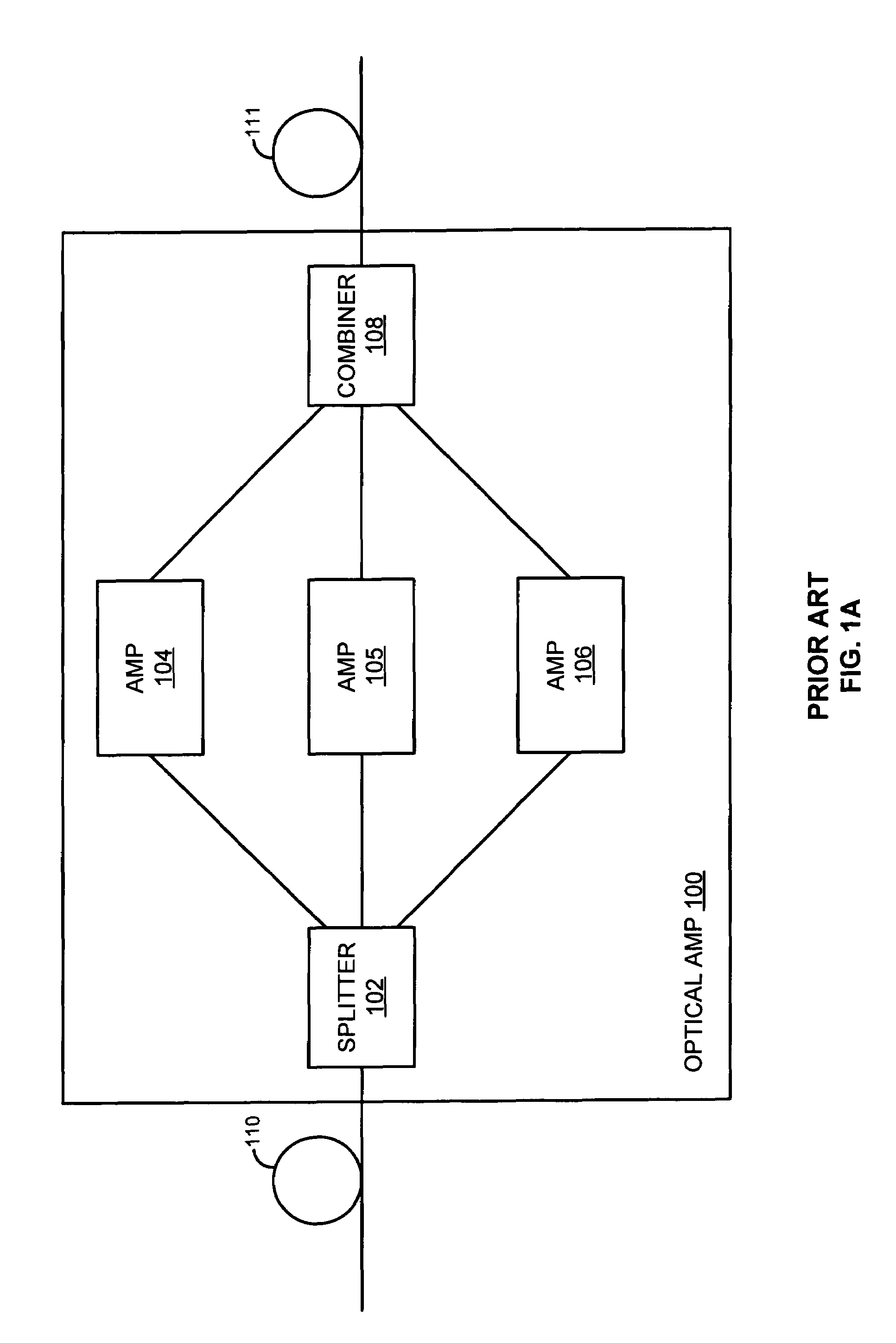
Although optical amplifier 100 generates a wider gain bandwidth, splitter 102, amplifiers 104–106, and combiner 108 can be expensive and complicated to implement.
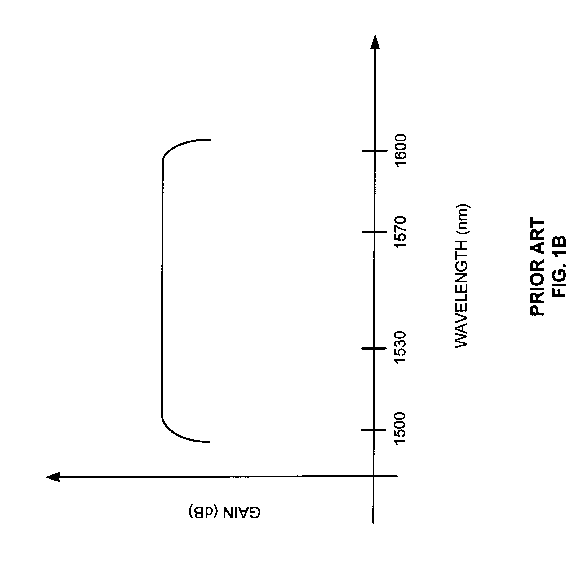
Although F-EDFA 200 generates a wider gain bandwidth than traditional EDFAs, the noise figure (NF) over the 100 nm gain bandwidth may be unacceptable, especially for the longer and shorter wavelength bands of the 100 nm gain bandwidth.
Unfortunately in current distributed / discrete amplifier configurations, the distributed amplifier and the discrete amplifier are set to amplify the same wavelengths.
Noise generated by either the discrete amplifier or the distributed amplifier may still cause problems for transmission distance.
If more gain is needed, the noise figure is not good enough, or a problem is encountered, then the other pump system can be turned on.
However, the noise figure may be undesirable for the L-band and the S-band.
The L-band and the S-band may not be able to be used to carry data over long distances because of the high noise figure.

Method used


Image

  • Distributed and discrete amplification of optical signals
  • Distributed and discrete amplification of optical signals
  • Distributed and discrete amplification of optical signals

Examples


example —

Example—FIGS. 6 and 7a–d

[0053]FIG. 6 illustrates another example of an optical amplifier system 600 in an example of the invention. Optical amplifier system 600 is comprised of a transmission fiber span 602, a Wavelength Division Multiplexer (WDM) 604, a pump system 606, a Fluoride-based Erbium-Doped Fiber Amplifier, (F-EDFA) 608, a transmission fiber span 610, a WDM 612, and a pump system 614. F-EDFA 608 and WDM 604 are coupled to fiber span 602. F-EDFA 608 and WDM 612 are coupled to fiber span 610. Pump system 606 is coupled to WDM 604. Pump system 614 is coupled to WDM 612.

[0054]Pump system 606 includes a 1400 nm pump 621 and a 1480 nm pump 622. Pump systems 614 includes a 1400 nm pump 623 and a 1480 nm pump 624. Pumps 621–624 may be conventional Raman pumps having a power of about 250 mW. The 1400 nm pumps 621 and 623 could be in the range of 1390 nm to 1410 nm, but 1400 nm is used as an approximation. Similarly, the 1480 nm pumps 622 and 624 could be in the range of 1470 nm to...


PUM


Abstract

An optical amplifier system is disclosed comprising a discrete amplifier system and a distributed amplifier system. The discrete amplifier system receives optical signals and amplifies the optical signals having wavelengths in a target wavelength band. The target wavelength band has a bandwidth of at least 80 nm. The distributed amplifier system amplifies the optical signals having wavelengths in a longer wavelength band of the target wavelength band, a shorter wavelength band of the target wavelength band, or both.

Description

BACKGROUND OF THE INVENTION [0001]1. Field of the Invention[0002]The invention is related to the field of communication systems, and in particular, to systems and methods of providing distributed and discrete amplification of optical signals.[0003]2. Statement of the Problem[0004]Many communication companies use fiber optic cabling as a media for transmitting data because of its high-bandwidth capacity. Fiber optic cables reliably transport optical signals over long distances. Over a distance, optical signals attenuate in the fiber due to Rayleigh scattering. The attenuation may be recovered by an optical amplifier. However, the optical amplifier adds noise to the optical signals. The noise accumulation on the optical signals can especially be a problem for ultra long haul transmissions.[0005]Optical amplifiers may be discrete amplifiers or distributed amplifiers. Distributed amplifiers use the transmission fiber carrying the optical signals as a gain medium. Discrete amplifiers do ...

Claims


Application Information

Patent Timeline
Patent Type & Authority Patents(United States)
IPC IPC(8): H01S3/00H01S3/30H04B10/17
CPCH04B10/2941H01S3/302
Inventor AKASAKA, YOUICHI
Owner SPRINT CORPORATION
Learn More