Wire grid polarizer with double metal layers

a polarizer and metal layer technology, applied in the field of polarizers, can solve the problems of not teaching the reference method of designing the polarizer with high quality extinction for the visible spectrum, the device only operates properly within narrow wavelength bands, and is rather angularly sensitive, so as to reduce resonance, the effect of high extinction ratio and high extinction ratio

Active Publication Date: 2007-01-02
IND TECH RES INST
View PDF6 Cites 98 Cited by
  • Summary
  • Abstract
  • Description
  • Claims
  • Application Information

AI Technical Summary

Benefits of technology

[0016]The present invention improves on the conventional technology in that the wire grid polarizer with double metal layers has the period of 10˜250 nm, the first or second thickness of 30˜150 nm, and the vertical distance of 10˜100 nm. Additionally, the ratio of the width to the period is 25˜75%. Thus, the polarizer according to the present invention can reduce resonance to achieve the high extinction ratio (>1000) for the visible spectrum. Furthermore, the polarizer maintains a high extinction ratio for use at large incident angles. Thus, it is useful for LCD applications and ameliorates the disadvantages of the conventional technology.

Problems solved by technology

That is, the reference does not teach how to design the polarizer with high quality extinction for the visible spectrum.
Furthermore, the device only operates properly within narrow wavelength bands (about 25 nm) and the device is rather angularly sensitive.
These considerations make the device unsuitable for broad wavelength bands in the visible spectrum.
The device is difficult to manufacture, however, as it requires at least six intra-wire layers.
Nevertheless, the extinction ratio of this device is unstable.

Method used


Image

  • Wire grid polarizer with double metal layers
  • Wire grid polarizer with double metal layers
  • Wire grid polarizer with double metal layers

Examples


first embodiment

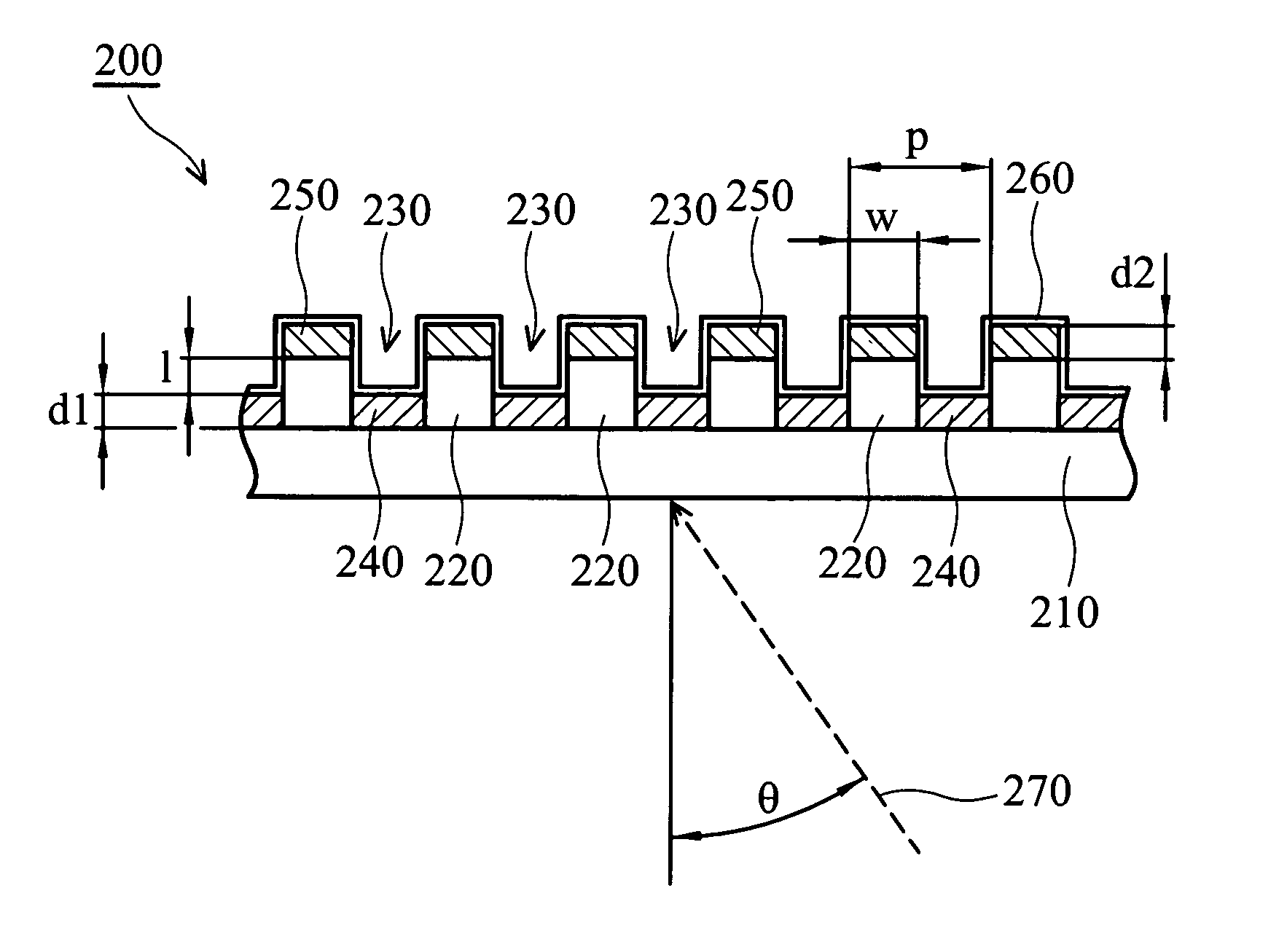
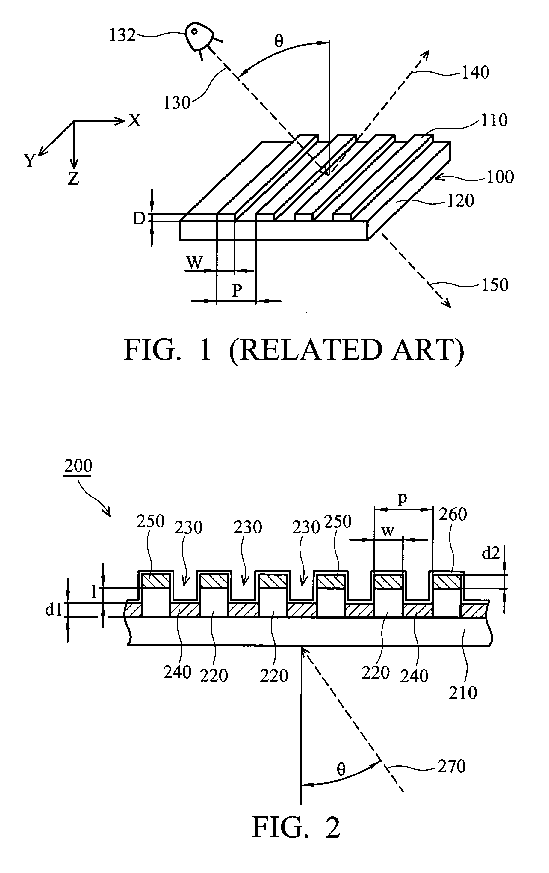
[0032]FIG. 2 is a sectional view of a wire grid polarizer 200 with double metal layers, according to the first embodiment of the present invention. The wire grid polarizer 200 comprises the following elements.

[0033]An insulating and transparent substrate 210 is provided. The transparent substrate 210 can be a glass or plastic substrate, wherein the plastic material is PC (polycarbonate), PMMA (polymethyl methacrylate), PS (polystyrene) or the like. The width of the transparent substrate 210 can be 500˜1500 μm. The refractive index (R.I.) of the transparent substrate 210 is, for example, about 1.5.

[0034]An array of parallel and elongated dielectric layer 220 overlies the transparent substrate 210, wherein the dielectric layer 220 have a period (p) and a trench 230 is located between adjacent dielectric layers 220. In the first embodiment, the transparent substrate 210 is exposed in the trench 230. The material of the dielectric layers 220 can be polymer, such as PMMA serving as photo...

second embodiment

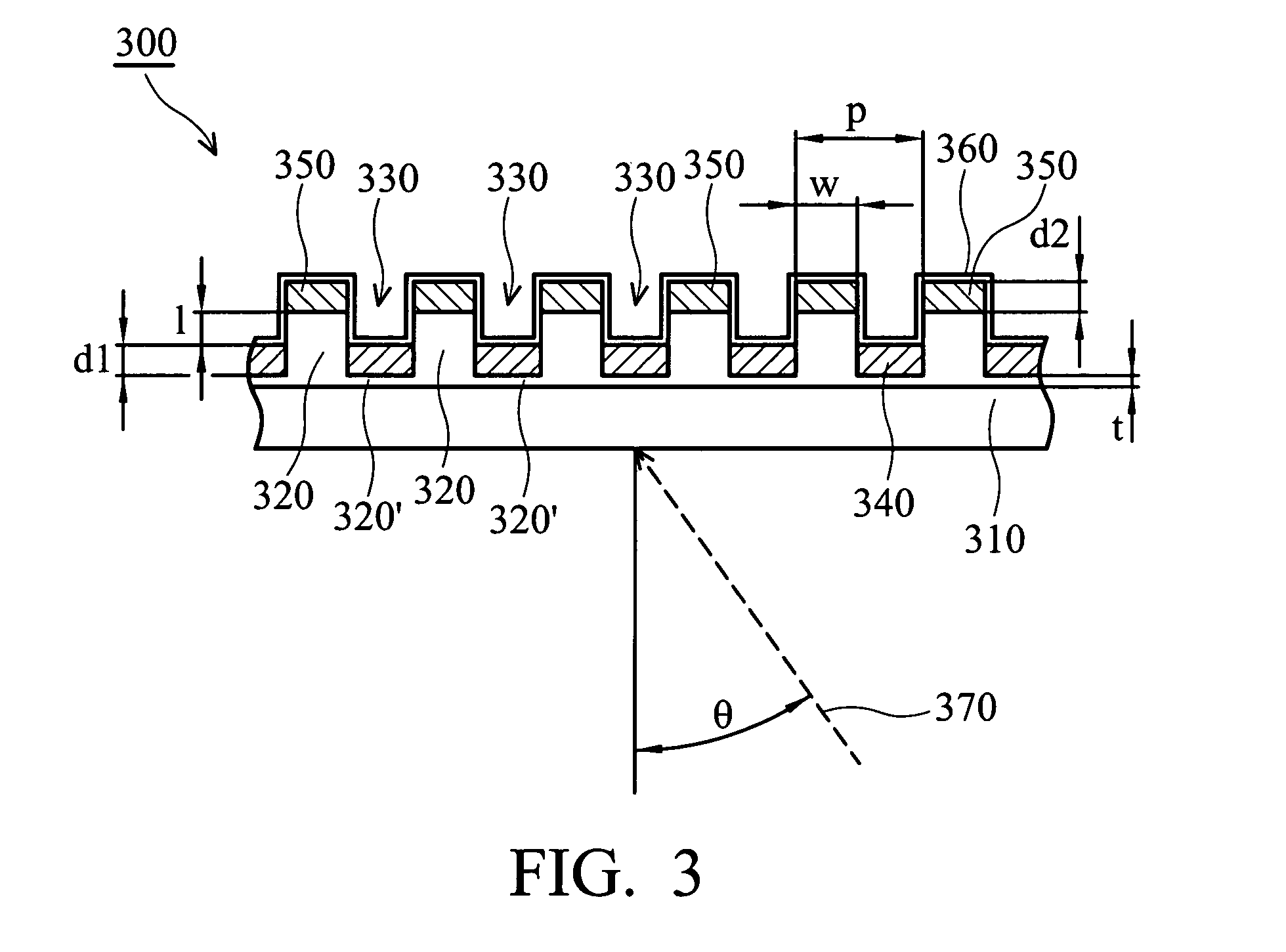
[0041]FIG. 3 is a sectional view of a wire grid polarizer 300 with double metal layers, according to the second embodiment of the present invention. The difference in the second embodiment is that the trench does not expose the transparent substrate. That is, a remaining dielectric layer is left in the trench. The wire grid polarizer 300 comprises the following elements.

[0042]An insulating and transparent substrate 310 is provided. The transparent substrate 310 can be a glass or plastic substrate, wherein the plastic material is PC (polycarbonate), PMMA (polymethyl methacrylate), PS (polystyrene) or the like. The width of the transparent substrate 310 can be 500˜1500 μm. The refractive index (R.I.) of the transparent substrate 310 is about 1.5.

[0043]An array of parallel and elongated dielectric layers 320 overlies the transparent substrate 310, wherein the dielectric layers 310 have a period (p) and a trench 330 is located between adjacent dielectric layers 320. In the second embodi...


PUM

PropertyMeasurementUnit
thicknessaaaaaaaaaa
vertical distanceaaaaaaaaaa
wavelengthsaaaaaaaaaa

Abstract

A wire grid polarizer with double metal layers for the visible spectrum. Parallel dielectric layers having a period (p) of 10˜250 nm and a trench between adjacent dielectric layers overlie a transparent substrate. A first metal layer having a first thickness (d1) of 30˜150 nm is disposed in the trench. A second metal layer having a second thickness (d2) of 30˜150 nm and a width (w) overlies on the top surface of each dielectric layer. The first and second metal layers are separated by a vertical distance (l) of 10˜100 nm. The first thickness (d1) is the same as the second thickness (d2). A ratio of the width (w) to the period (p) is 25˜75%.

Description

BACKGROUND OF THE INVENTION[0001]1. Field of the Invention[0002]The present invention relates to a polarizer which provides a very high extinction ratio (>1000), and more particularly, to a wire grid polarizer with double metal layers for use in visible spectrum and a fabrication method thereof.[0003]2. Description of the Related Art[0004]The use of an array of parallel conducting wires to polarize radio waves dates back more than 110 years. Wire grids, generally in the form of an array of thin parallel conductors supported by a transparent substrate, have also been used as polarizers for the electromagnetic spectrum.[0005]FIG. 1 illustrates a conventional wire grid polarizer. The wire grid polarizer 100 comprises a multiplicity of parallel conductive electrodes 110 supported by a dielectric substrate 120. This device is characterized by the grating spacing or pitch or period of the conductors 110, designated as P; the width of the individual conductors 110, designated as W; and ...

Claims


Application Information

Patent Timeline
Patent Type & Authority Patents(United States)
IPC IPC(8): G02B27/28G02B5/30
CPCG02B5/3058
Inventor CHIU, CHIH-HOKUO, HUI-LUNGLIU, YI-CHUNCHEN, PING-CHEN
Owner IND TECH RES INST
Why Eureka
Try Eureka