Electronic control unit

a control unit and electronic technology, applied in the direction of printed circuit assembling, coupling device connection, braking components, etc., can solve the problems of reducing the stress of the soldering juncture portion, unable to separate the juncture portions of the two lead portions from the circuit board, and unable to flexibly connect the juncture portions to the fixing portion, etc., to achieve the effect of reducing the stress

Inactive Publication Date: 2007-01-02
ADVICS CO LTD
View PDF8 Cites 16 Cited by
  • Summary
  • Abstract
  • Description
  • Claims
  • Application Information

AI Technical Summary

Benefits of technology

[0008]Accordingly, it is a primary object of the present invention to provide an improved electronic control unit capable of preventing juncture portions of plural lead portions of a bus bar to a circuit board from being damaged by reducing stresses which are developed at the juncture portions with a change in temperature.
[0009]Briefly, in an electronic control unit according to the present invention, a chassis having a plate portion protrudes a side wall from the circumference of the plate portion, and a circuit board is secured to a board-side attaching surface of the plate portion opposite to a surface from which the side wall protrudes. The circuit board extends substantially in parallel to the board-side attaching surface with a predetermined space secured therebetween. A housing incorporating at least one device mounts the chassis on a surface thereof with an end surface of the side wall being in contact with the surface of the housing. A bus bar is further provided, which includes a base portion having a fixing portion at a part thereof fixed to the plate portion and connected to a lead of the at least one device taken out from the housing. The base portion also has plural branch portions thereon. Plural lead portions respectively extend from the plural branch portions of the base portion to be joined at end portions thereof to the circuit board. Plural elastic portions for reducing stresses which are developed respectively at juncture portions of the lead portions to the circuit board as the temperature changes, are provided between the branch portions and the fixing portion of the base portion alongside of the board-side attaching surface.
[0010]With this construction, the circuit board for the electronic control unit is secured to the board-side attaching surface of the plate portion of the chassis, with a predetermined space secured relative to the plate portion, and the bus bar is fixed at the fixing portion to the board-side attaching surface so that the branch portions at which plural lead portions branch from the base portion are defined at free ends of the base portion. Since the branch portions of the base portion are defined at the free ends of the same and since the elastic portions are formed between the branch portions and the fixing portion substantially in parallel to the board-side attaching surface, those parts which extend between the juncture portions of the lead portions to the circuit board and the branch portions at which the lead portions are branched from the base portion are flexibly separated from each other. Thus, stresses which are developed at the juncture portions of the lead portions to the circuit board as the temperature changes can be reliably reduced through the elastic portions, whereby the juncture portions can be prevented from being broken or damaged.
[0012]With this construction, the base portion of the bus bar which is fixed at its fixing portion to the base-side attaching surface is provided with the crank portion at a position close to the fixing portion and is further provided with the flexible portions corresponding respectively to the lead portions, between the crank portion and the branch portions substantially in parallel to the board-side attaching surface. Therefore, stresses which are developed at the juncture portions of the lead portions to the circuit board as the temperature changes can be reliably reduced through the crank portion and the flexible portions which are arranged in a narrow space between the board-side attaching surface and the circuit board, whereby the juncture portions can be prevented from being broken or damaged.

Problems solved by technology

Where such a bus bar large in width and thickness is joined by soldering to a circuit board without being changed in dimension and shape, the thermal expansion of the bus bar due to a temperature change would cause the soldered juncture portion to be cracked or broken.
In this case, because of being large in width and thickness, the bus bar cannot be embeded in the plate portion of the chassis.
However, in accordance with the technology described in the foregoing United States patent, it is unable to separate the juncture portions of the two lead portions to the circuit board and to flexibly connect the juncture portions respectively to the fixing portion.

Method used


Image

  • Electronic control unit
  • Electronic control unit
  • Electronic control unit

Examples


first embodiment

[0019](First Embodiment)

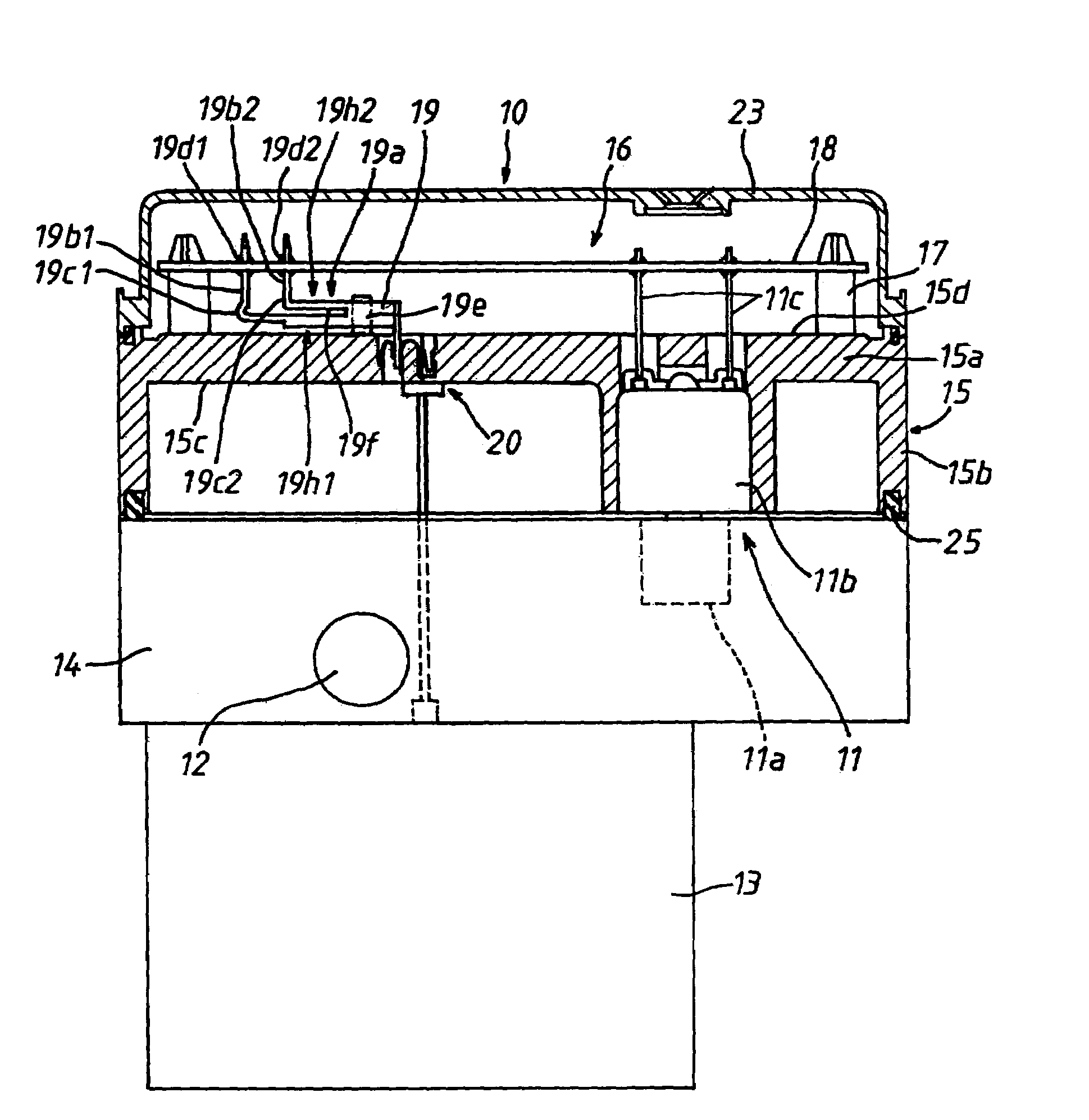
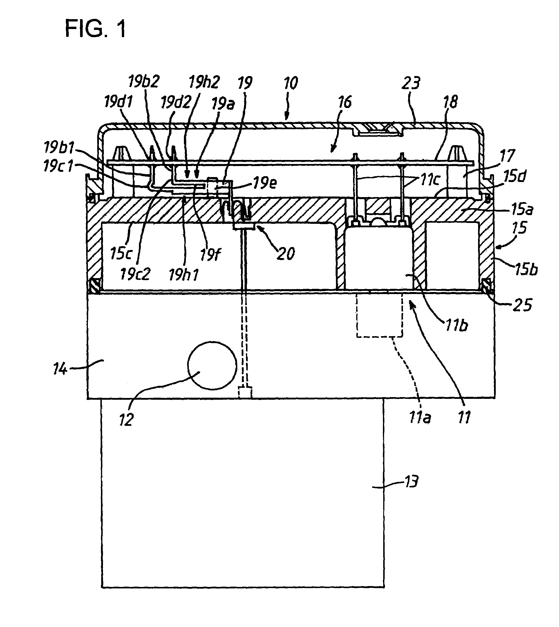
[0020]Hereafter, an electronic control unit 16 in a first embodiment according to the present invention will be described with reference to FIGS. 1 and 2 taking an example which is applied to a pressure regulating device 10 for controlling the pressure of oil supplied to each of wheel cylinders in an antiskid brake system for a motor vehicle (not shown). The pressure regulating device 10 is composed of a solenoid valve 11 for controlling the pressure of oil to be supplied to the wheel cylinders; a housing 14 incorporating various equipments or devices such as an oil pump 12, an electric motor 13 for driving the oil pump 12, and the like; and an electric control unit 16 including a circuit board 18 which is secured to a case or chassis 15 fixed to the housing 14, and the like. The housing 14 contains a valve portion 11a of the solenoid valve 11, the oil pump 12 and so forth inside thereof and has secured to its reverse surface the electric motor 13 for driving...

second embodiment

[0025](Second Embodiment)

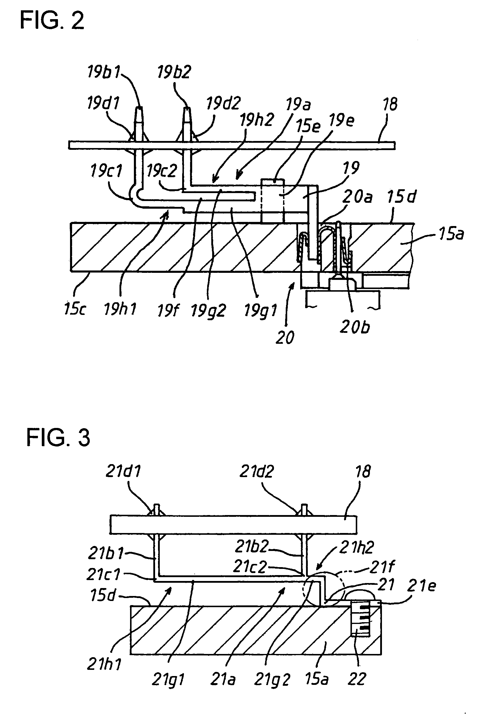
[0026]An electronic control unit in a second embodiment is different from that in the foregoing first embodiment in the shape of elastic portions formed on a bus bar as well as in the manner of fixing the bus bar onto the board-side attaching surface 15d. Therefore, the second embodiment so different from the foregoing first embodiment will be described with reference to FIG. 3 with respect to such differences only. A bus bar 21 is detachably fixed to the board-side attaching surface 15d with a fixing portion 21e of a base portion 21a thereof fixed by means of a bolt 22 to the board-side attaching surface 15d. The base portion 21a is bent at an end of the fixing portion 21e at right angle in a direction going way from the board-side attaching surface 15d and is further bent at right angle to space a predetermined distance from the board-side attaching surface 15d and to extend in parallel to the same so that a crank portion 21f is formed. A flexible portion ...


PUM


Abstract

In an electronic control unit, a chassis is provided with a plate portion, and a circuit board is secured to a board-side attaching surface of the plate portion with a predetermined space secured relative to the plate portion. The chassis is further provided with a side wall protruding from the circumferential portion of the other surface of the plate portion and is mounted on a surface of a housing incorporating a device therein, with an end surface of the side wall being seated on the surface of the housing. A bus bar is fixed at a fixing portion thereof to the board-side attaching surface between the plate portion and the circuit board and is connected to a terminal of the device which is taken out from the housing. The bus bar is provided at plural free ends thereof with branch portions at which lead portions extend to be joined at end portions thereof to the circuit board. Elastic portions for reducing stresses which are developed at juncture portions of the lead portions to the circuit board as the temperature changes are formed between the base portion and the branch portions alongside the board-side attaching surface.

Description

[0001]This application is based on and claims priority under 35 U.S.C. 119 with respect to Japanese Application No. 2003-279989 filed on Jul. 25, 2003, the entire content of which is incorporated herein by reference.BACKGROUND OF THE INVENTION[0002]1. Field of the Invention[0003]The present invention relates to an electronic control unit capable of reducing the stress which is developed at juncture portions between a circuit board secured to a chassis of the electronic control unit and lead portions of a bus bar as the temperature changes.[0004]2. Discussion of the Related Art[0005]In a known electronic control unit of this kind as disclosed in U.S. Pat. No. 6,155,856 (equivalent of Japanese unexamined, published patent application No. 2000-164276), a circuit board is fixed with a predetermined distance secured relative to a board-side attaching surface of a plate portion of a chassis or case. A fixing portion of each connector terminal is inserted into an insertion hole from a reve...

Claims


Application Information

Patent Timeline
Patent Type & Authority Patents(United States)
IPC IPC(8): G06F1/16B60T15/18H01R13/14H01R13/24H02G3/16H05K1/02H05K3/30H05K3/34H05K5/02
CPCH05K3/308B60T8/3675H05K5/0247H01R9/091H01R13/24H05K1/0263H05K2201/0979H05K2201/10272H05K2201/10848H05K3/3447Y10T137/87885Y10T137/8326
Inventor SANADA, SATOSHITSUNOOKA, TAKAOTSURUTA, MATSUHISA
Owner ADVICS CO LTD
Why Eureka
Try Eureka