Multiple mode data communication system and method and forward and/or reverse link control channel structure

Active Publication Date: 2007-01-02
LUCENT TECH INC
View PDF14 Cites 310 Cited by
  • Summary
  • Abstract
  • Description
  • Claims
  • Application Information

AI Technical Summary

Benefits of technology

[0011]The present invention involves a multiple mode data communication system and method with the flexibility to schedule wireless unit transmissions and/or allow the wireless unit to transmit autonomously. In certain embodiments, the wireless units can transmit autonomously and/or use scheduling depending on the data rate, the length of the data packet or the type of data. For example, the wireless units can transmit autonomously at lower data rates and use scheduling at higher data rates. Thus, the multiple mode system enables wireless unit transmissions to be scheduled and/or be transmit autonomously, and wireless units can simultaneously operate in different scheduling and/or autonomous modes. Depending on the embodiment, the system can provide even greater flexibility in operation by permitting wireless units to be scheduled by a single base station, scheduled by a multiplicity of base stations simultaneously or otherwise, via coordination between base stations, scheduled by a multiplicity of base stations in an uncoordinated and asynchronous manner, allowed to transmit autonomously, and/or allowed to transmit autonomously under base station supervision (i.e. rate control/adjustment by the base station).
[0012]In accordance with another aspect of t

Problems solved by technology

Due to the delay-intolerant nature of voice communication, wireless units in conventional cellular systems transmit and receive over dedicate

Method used


Image

  • Multiple mode data communication system and method and forward and/or reverse link control channel structure
  • Multiple mode data communication system and method and forward and/or reverse link control channel structure
  • Multiple mode data communication system and method and forward and/or reverse link control channel structure

Examples


case 1

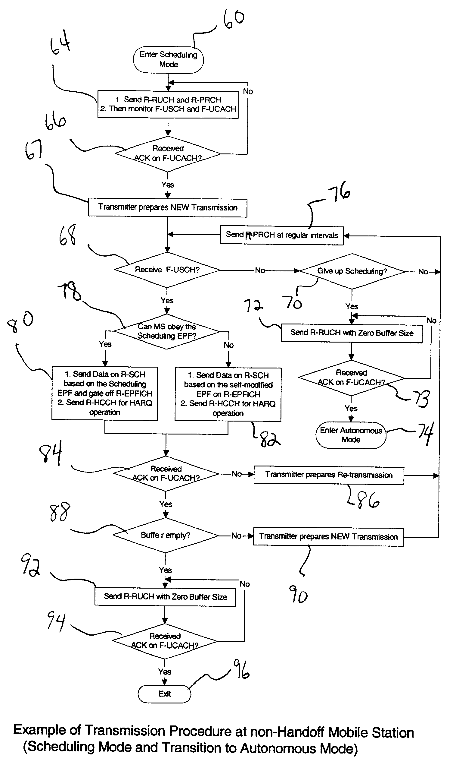
[0043] Scheduled Operation (Non-Handoff)

[0044]1. Wireless unit transmits the R-RUCH and the R-PRCH (buffer status and implied path loss to base station)

[0045]2. Base Station responds on the R-UCACH with an acknowledgement

[0046]3. Wireless unit continues to resend the R-PRCH at regular intervals

[0047]4. Base Station sends schedule grant to mobile at some subsequent time, on the F-USCH

[0048]5. Wireless unit transmits R-SCH (the actual data), R-HCCH, and the R-PRCH. The R-EPFICH is also sent if it cannot maintain the data format indicated by the base station on the F-USCH.

[0049]6. Base Station Acknowledges on the F-UCACH

[0050]7. Wireless unit waits for next schedule grant or sends R-RUCH with all zeros to indicate empty buffers (optional)

[0051]FIG. 6 shows a flow diagram of a case 1 embodiment of how the processing circuitry in a non-handoff wireless unit uses the control channel structure to operate using the multiple mode data communication system in a scheduling mode with a transiti...

case 1a

[0053] Scheduled Operation (Non-Handoff with Waiting Period Option Enabled)

[0054]1. Wireless unit transmits the R-RUCH and the R-PRCH (buffer status and implied path loss to base station)

[0055]2. Base Station responds on the R-UCACH with Waiting Period Indicator.

[0056]3. Wireless unit monitors F-USCH for scheduling information. During the waiting period, the R-PRCH is sent only when there is a significant improvement on the path loss. The R-PRCH is sent at the end of the waiting period if the mobile has not yet been scheduled.

[0057]4. Base Station sends schedule grant to wireless unit at some subsequent time, on the F-USCH.

[0058]5. Wireless unit transmits R-SCH (the actual data), R-HCCH, and the R-PRCH. The R-EPFICH is also sent if it cannot maintain the data format indicated by the base station on the F-USCH.

[0059]6. Base Station Acknowledges on the F-UCACH. Here the UCACH bit serve to acknowledge successful or unsuccessful reception of the user's data burst transmission.

[0060]7. W...

case 2

[0064] Maintaining Scheduling and Reception During Handoff

[0065]1. All wireless unit data bursts are accompanied by the R-EPFICH and R-HCCH. Thus all base stations in the active set know the format of the wireless unit's transmission and can decode it. This information is essential since none of the base stations can be certain apriori, as to the format and state (new or continued transmission) of the wireless unit's transmission.

[0066]2. The R-PRCH may or not be transmitted at regular intervals. If it is transmitted, the frequency of this transmission may be changed (lowered or set to zero) when the wireless unit in is handoff (via an upper layer message during data call setup).

[0067]3. Either one or all the base stations send the schedule grant to the wireless unit on their respective F-USCH and acknowledge the wireless unit's transmissions on their respective F-UCACH. If the schedule grants and acknowledgements are simultaneous, the wireless unit follows a rule to determine its t...


PUM


Abstract

A multiple mode data communication system and method provides the flexibility to schedule wireless unit transmissions and/or allow the wireless unit to transmit autonomously. In certain embodiments, the wireless units can transmit autonomously and/or use scheduling depending on the data rate, the length of the data packet or the type of data. For example, the wireless units can transmit autonomously at lower data rates and use scheduling at higher data rates. Thus, the multiple mode system enables wireless unit transmissions to be scheduled and/or be transmit autonomously, and wireless units can simultaneously operate in different scheduling and/or autonomous modes. Depending on the embodiment, the system can provide even greater flexibility in operation by permitting wireless units to be scheduled by a single base station, scheduled by a multiplicity of base stations simultaneously or otherwise, via coordination between base stations, scheduled by a multiplicity of base stations in an uncoordinated and asynchronous manner, allowed to transmit autonomously, and/or allowed to transmit autonomously under base station supervision (i.e. rate control/adjustment by the base station). Additionally, a forward and/or reverse link control channel structure is provided which can be used to implement the multiple mode data communication system and/or support various features enabling increased throughput over a shared data channel in a wireless communications system.

Description

BACKGROUND OF THE INVENTION[0001]1. Field of The Invention[0002]This invention relates to wireless communications and, more particularly, to a multiple mode data communication system and method and a forward and / or reverse link control channel structure to support various features.[0003]2. Description of Related Art[0004]Wireless communications systems include conventional cellular communication systems which comprise a number of cell sites or base stations, geographically distributed to support transmission and receipt of communication signals to and from wireless units which may actually be stationary or fixed. Each cell site handles voice communications over a particular region called a cell, and the overall coverage area for the cellular communication system is defined by the union of cells for all of the cell sites, where the coverage areas for nearby cell sites overlap to some degree to ensure (if possible) contiguous communications coverage within the outer boundaries of the ...

Claims


Application Information

Patent Timeline
IPC IPC(8): H04B7/212H04Q7/20H04B7/26H04J3/00H04L1/00H04L1/18H04W74/02
CPCH04L1/0002H04W74/02H04L1/1845H04L1/1819H04W72/02H04L1/00H04B7/26
Inventor KADABA, SRINIVAS R.KHAN, FAROOQ ULLAHPITTAMPALLI, ESHWARRUDRAPATNA, ASHOK N.SUNDARAM, GANAPATHY SUBRAMANIANVASUDEVAN, SUBRAMANIANYANG, YUNSONG
Owner LUCENT TECH INC
Why Eureka
Try Eureka