Solid core optic fiber and method for the production thereof

a solid core, optic fiber technology, applied in the direction of cladded optical fibre, instruments, other domestic articles, etc., can solve the problems of uneven layer thickness, kink formation in teflon, and comparatively more expensive production of optical insulated cores with tb-2 layers, etc., to achieve the effect of comparatively easy removal

Inactive Publication Date: 2007-01-02
CCS TECH INC
View PDF9 Cites 29 Cited by
  • Summary
  • Abstract
  • Description
  • Claims
  • Application Information

AI Technical Summary

Benefits of technology

[0005]It is the objective of the present invention, to specify an optical insulated core, where the core jacket can be removed comparatively easily from the coating of the optical fiber while avoiding the disadvantages listed above.
[0009]This results in the advantage, that the manufacturing costs compared to a core construction with a Teflon separating layer are significantly reduced, because the comparatively expensive Teflon is eliminated, the investment costs are minimized due to the one-step process and the time necessary for manufacture of the insulated core is decreased. For manufacture of the insulated core according to the invention only one extrusion line and one extrusion process are necessary. In comparison to the manufacture of an insulated core with a Teflon layer, the extrusion speed during application of the PVC core jacket onto the coated optical fiber can be significantly increased, for example from a speed of 140 m / min for manufacture of an insulated core with a Teflon layer to a speed greater than 300 m / min for the manufacture of an insulated core according to the invention.

Problems solved by technology

An optical insulated core with a TB-2 layer is comparatively more expensive to produce, especially the application of the different layers is comparatively costly.
During application of the layers in one work process, the danger exists for an uneven layer thickness and formation of kinks in the Teflon due to abrasion in the extruder tool.
Additionally, due to voids where there is no Teflon, localized attenuation peaks can occur.
Furthermore, generally only a limited pay-off speed is possible during the extrusion process.
With a 2-step extrusion process, where the Teflon layer is applied first followed by the PVC core jacket, additional investment costs are incurred due to the necessary expansion of the extrusion lines.
Handling problems can also be created, since the Teflon layer is commonly formed as a 3-component mixture and the components contain hazardous elements.

Method used


Image

  • Solid core optic fiber and method for the production thereof
  • Solid core optic fiber and method for the production thereof

Examples


Embodiment Construction

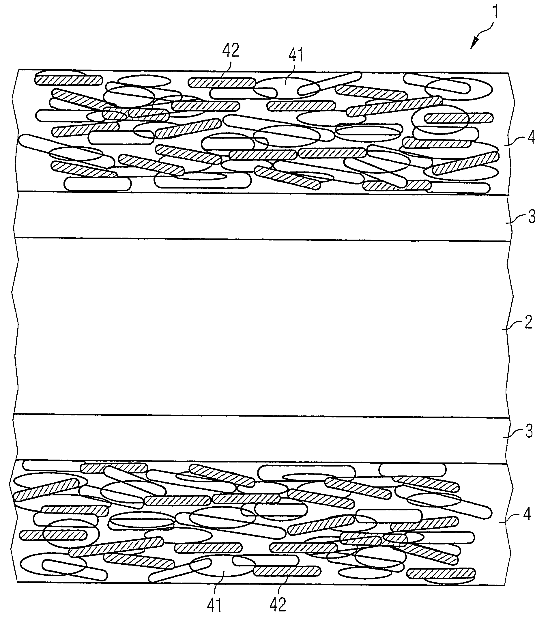
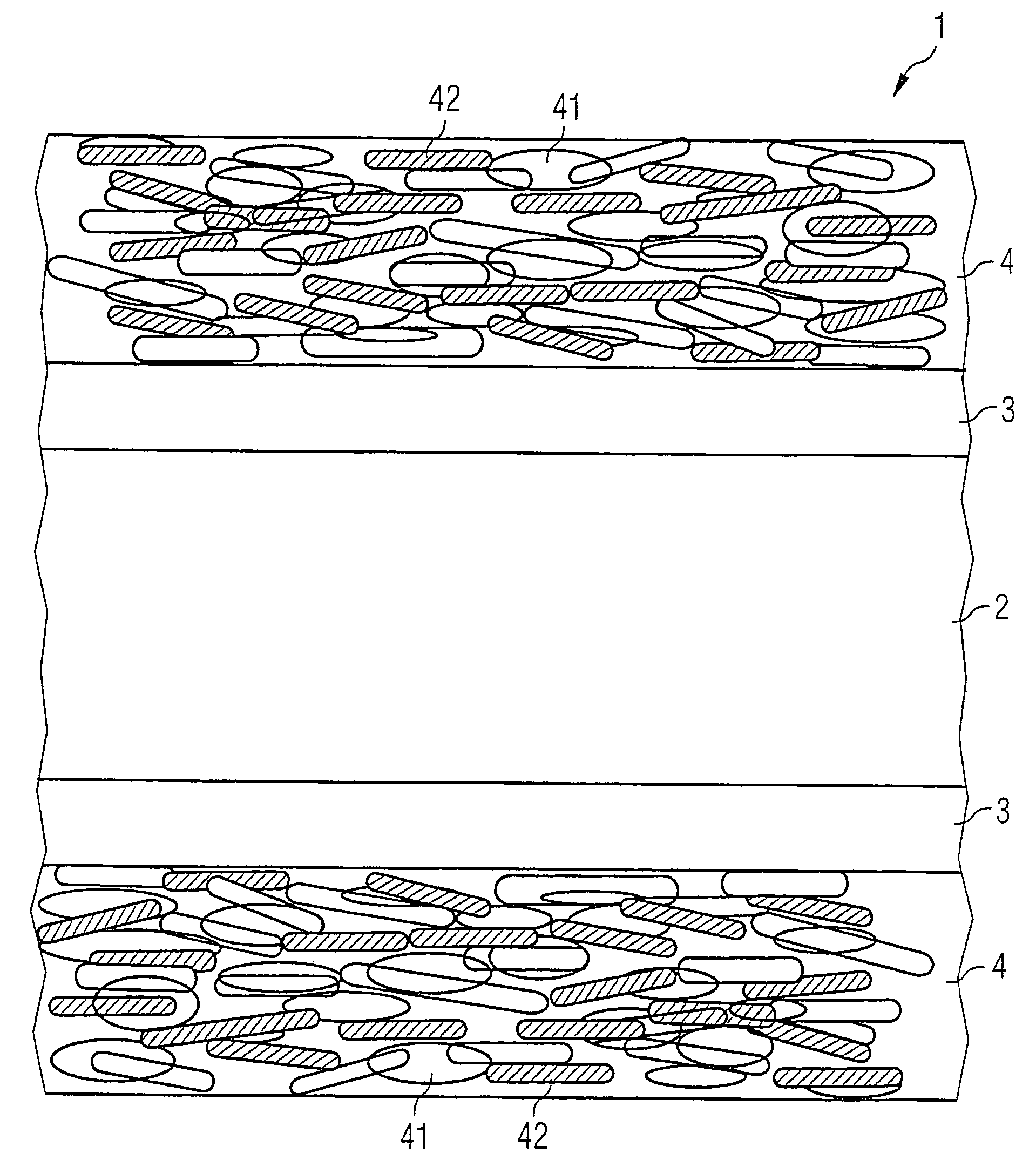
[0013]In a preferred construction sample of the invention a high molecular polysiloxane formulation is mixed into the core jacket material. This formulation has a molecular chain length greater than approximately 100,000 polymerized monomers. It was especially advantageous to mix HTV silicone rubber (high temperature-vulcanized silicone rubber) based on polydimethylvinyl-siloxane into the core jacket material.

[0014]In a further construction sample of the invention, a component is mixed into the core jacket material, which shows an aversion to or incompatibility with the coating of the optical fiber due to its chemical composition and thus produces the separating effect against the coating of the optical fiber. Such a component can, for example, be chlorinated polyethylene (CPE).

[0015]In a further construction sample of the invention a mineral lubricant or separation element, especially in the form of a high-dispersion silicone dioxide (Sipemat 44) or a talcum product is mixed into t...


PUM

PropertyMeasurementUnit
speedaaaaaaaaaa
speedaaaaaaaaaa
molecular chain lengthaaaaaaaaaa

Abstract

An optical insulated core with a coated optical fiber (2) shows a core jacket (4) with a core jacket material containing polyvinylchloride (41) which is applied to the coating of the optical fiber. It contains a solid component (42) distributed within the core jacket material, which produces a mechanical separation effect against the coating of the optical fiber. The solid component (42) is mixed and distributed into the core jacket material during a compounding process. Thus the core jacket can be removed from the coating of the optical fiber in a simple way.

Description

FIELD OF THE INVENTION[0001]The present invention concerns an optical insulated core as well as a process for the manufacture of such an optical insulated core.BACKGROUND OF THE INVENTION[0002]In order to keep optical fibers in the form of optical glass fibers free from outside influences, optical fibers are generally protected by a jacket. A simple possibility to protect optical fibers in the form of glass fibers against outside influences consists of providing the optical fiber with a coating and immediately applying a firm protective jacket made of a suitable plastic over the coating of the optical fiber. Such an arrangement is commonly designated as an insulated core or filled core. Such a core construction distinguishes itself by a substantial decrease of the outer diameter of the core in contrast to a loose tube.[0003]Especially for the installation and connectorization it is necessary to remove the core jacket of an insulated core from the optical fiber. To make it easier to ...

Claims


Application Information

Patent Timeline
Patent Type & Authority Patents(United States)
IPC IPC(8): G02B6/02G02B6/36G02B6/44B29C48/06B29D11/00C03C25/10C03C25/1065C03C25/47
CPCB29D11/00663G02B6/4402C03C25/101C03C25/1065B29C47/0004B29C47/0016B29K2105/06C03C25/47B29C48/022B29C48/06
Inventor WILL, NADJAWILL, HOLGERSCHUCHMANN, JOACHIMTISCHER, SWEN
Owner CCS TECH INC
Why Eureka
Try Eureka