Apparatus, method and system for gas turbine engine noise reduction

a gas turbine engine and noise reduction technology, applied in the field of aircraft gas turbine engines, can solve the problems of prohibitive long-range aircraft performance losses, undesirable noise levels of gas turbine engines used in aircraft, etc., and achieve the effect of reducing the noise of gas turbine engines and minimizing aircraft cruise performance losses

Inactive Publication Date: 2007-01-09
ROHR INC
View PDF22 Cites 43 Cited by
  • Summary
  • Abstract
  • Description
  • Claims
  • Application Information

AI Technical Summary

Benefits of technology

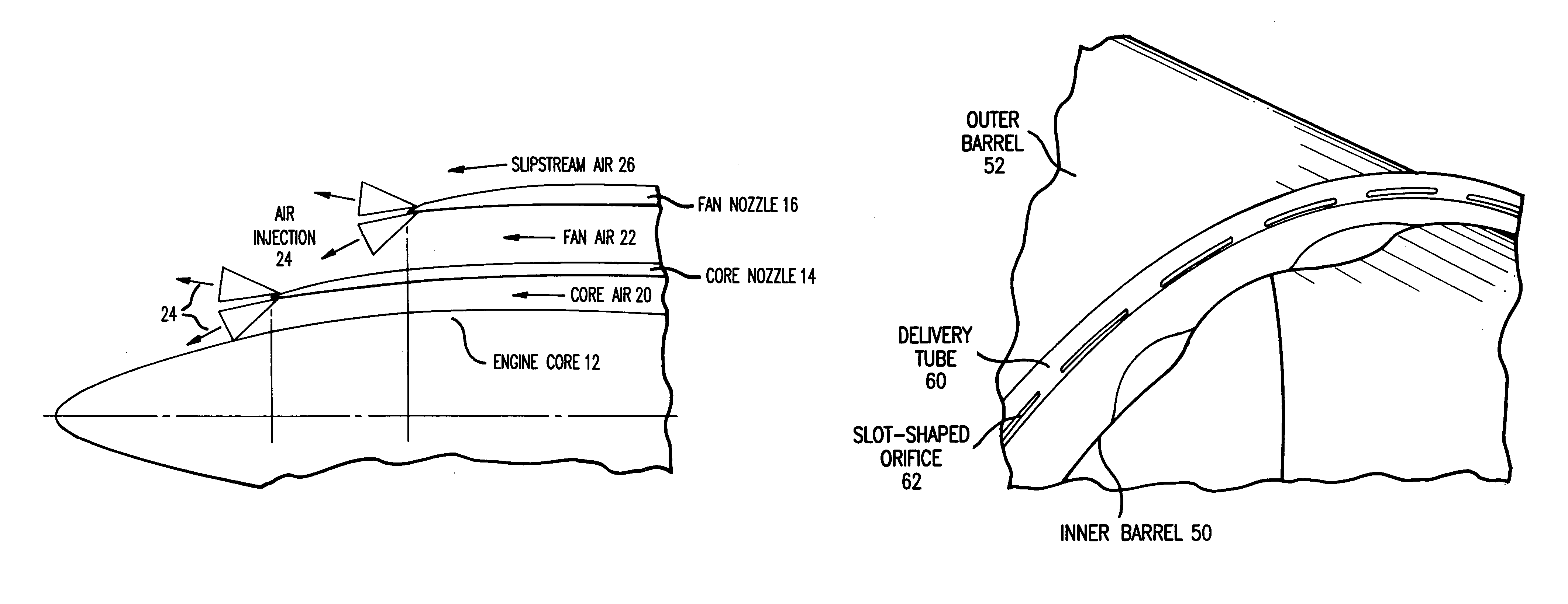
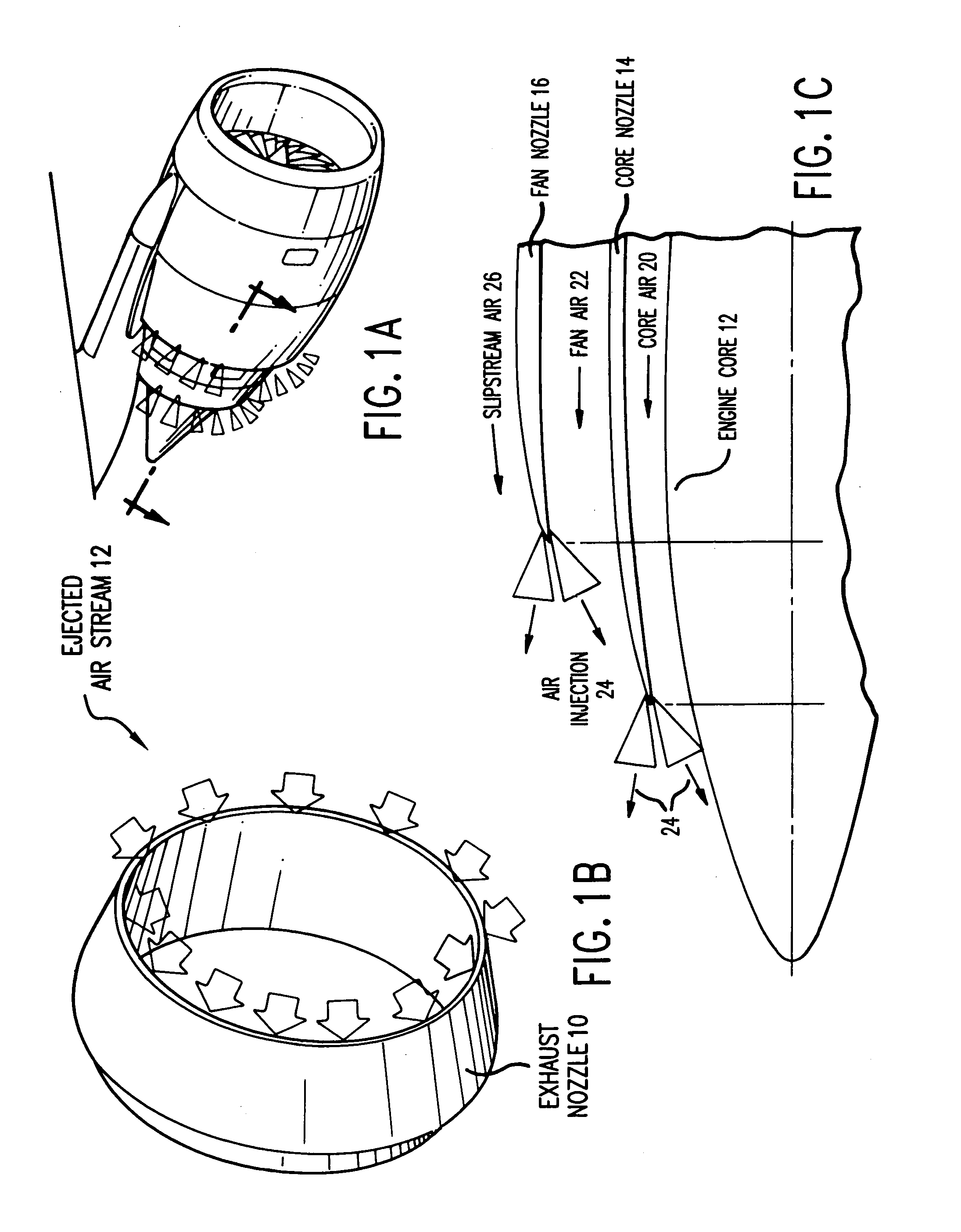
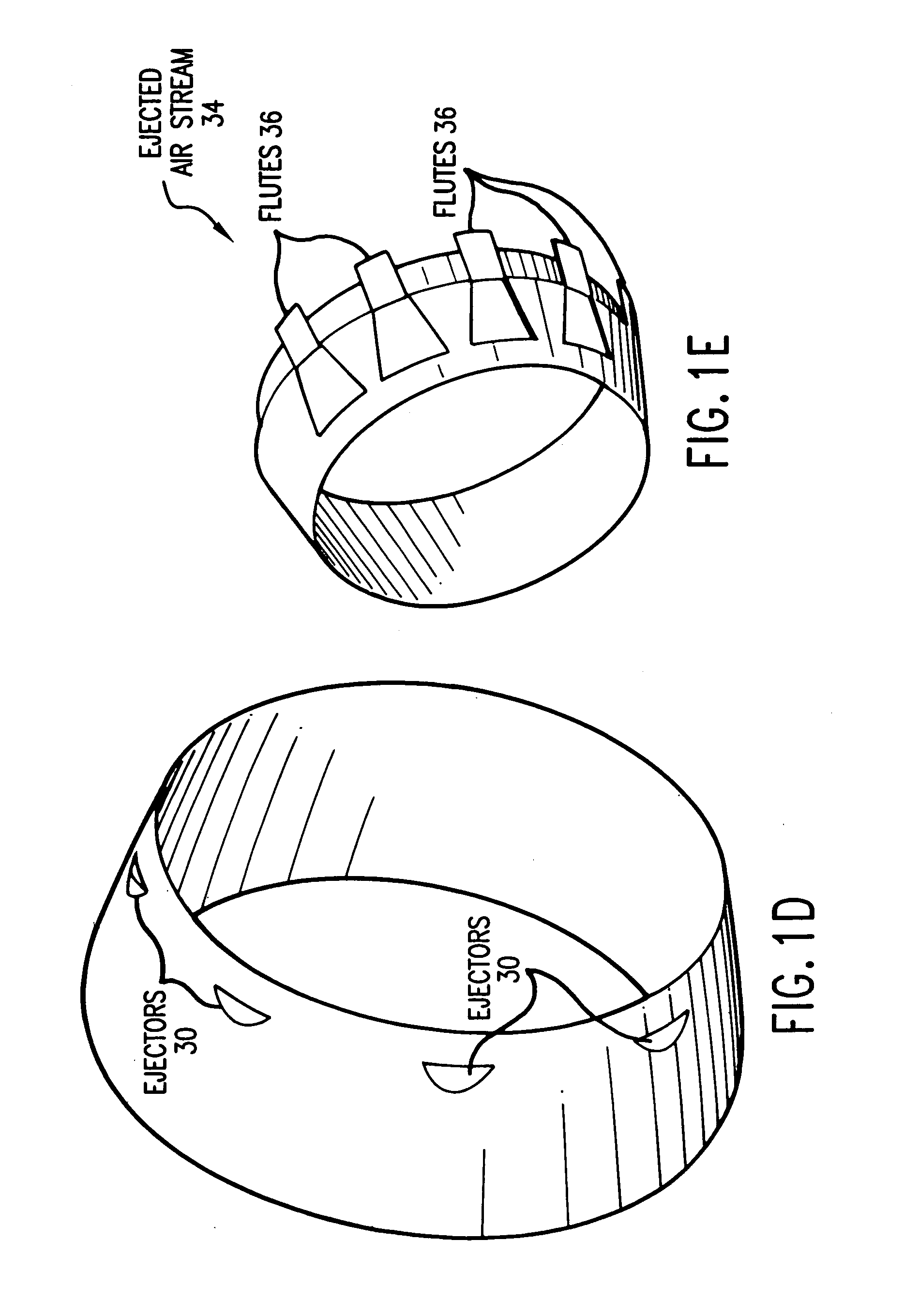
[0007]This invention is directed to an apparatus, method and system for reducing gas turbine engine noise, such as noise generated by an aircraft gas turbine engine particularly during high noise generating periods such as aircraft takeoff, while minimizing aircraft cruise performance losses. More specifically, in the apparatus of this invention a separate gas stream, preferably high pressure air such as engine bleed air, diverted core air or air from a pressurized storage container or a combination thereof is introduced in an area proximate to one or more engine nozzle portions to disrupt the noise-generating gas streams ordinarily generated by the engine exhaust and the travel of the airplane through the air. The gas may be injected using, for example, at least one gas injector which introduces the gas in the desired area The gas may be as a steady or continuous stream, or may be injected in a pulsing manner in which either all of the injectors pulse simulataneously or the injectors pulse sequentially around the perimeter of the engine nozzle portion or portions. Alternatively, one or more synthetic jet actuators located proximate to at least one trailing edge of at least one engine nozzle portion may be used to introduce the desired gas stream into the desired location. The gas injector or injectors and one or more synthetic jet actuators may also be used in combination to achieve the desired gas injection. The apparatus of this invention comprises at least one, and preferably a plurality of, gas injectors, synthetic jet actuators or combinations thereof for introducing gas into the area proximate to one or more engine nozzle portions. Various configurations and locations for the gas injectors, synthetic jet actuators, or combinations thereof, as described herein, may be employed to achieve the desired noise reduction.
[0008]The method of this invention is a method for reducing noise generated by an aircraft gas turbine engine, the method comprising:
[0011]In the system of this invention, noise generated by an aircraft gas turbine engine is reduced using a system comprising:
[0014]In the method and system of this invention, the introduction of gas such as air into the apparatus is preferably halted during the cruise portion of the aircraft flight to avoid or reduce performance losses.

Problems solved by technology

More particularly, it is well known that gas turbine engines used in aircraft generate undesirable noise levels, particularly during the takeoff period of the aircraft.
However, the performance losses associated with the use of such tabs and chevrons becomes prohibitive for long range aircraft where cruise performance is the driving design parameter.

Method used


Image

  • Apparatus, method and system for gas turbine engine noise reduction
  • Apparatus, method and system for gas turbine engine noise reduction
  • Apparatus, method and system for gas turbine engine noise reduction

Examples


example 1

[0046]A test apparatus was built to examine the effect of different tab designs. The apparatus consisted of two transition ducts and three different mixer designs. The ducts were attached to a preexisting airflow facility. The overall test setup is shown in FIG. 2.

Control Valve Arrangement

[0047]The airflow facility consisted of a series of pipes that attached to 4 large reservoir tanks. The pipes supply to various test facilities. For the described test, an 8″ stub-off was used for testing. Air from the 8″ stub-off flowed through two diverging branches, each of which was 5″ in diameter. Air for the air tab nozzle was supplied from a 1″ stub-off from the main supply line. The arrangement is shown in greater detail in FIG. 3.

Transition Ducts

[0048]Transition ducts were mounted at the end of the 5″ lines. The ducts were constructed to represent fan and core stream mass flows. Because each 5″ line was from the same supply line, the test configuration only allowed for cold flow testing. T...


PUM


Abstract

An apparatus for reducing gas turbine engine noise, such as noise generated by an aircraft gas turbine engine, comprises at least one and preferably a plurality of gas injectors for injecting gas such as high pressure engine bleed air, diverted core air, air obtained from a pressurized storage container or air obtained from a synthetic jet actuator into the area proximate to one or more engine nozzle portions, thereby disrupting the noise-generating gas streams generated by the engine exhaust and the travel of the airplane through the air. The apparatus is particularly useful for reducing engine noise during the takeoff period of aircraft flight.

Description

CROSS-REFERENCE TO RELATED APPLICATIONS[0001]This is a national application for International Application No. PCT / US01 / 30862, which was filed on Oct. 2, 2001 and which published in English on Apr. 11, 2002, which in turn claims priority from U.S. Provisional Application Ser. No. 60 / 237,314, which was filed on Oct. 2, 2000.BACKGROUND OF THE INVENTION[0002]1. Field of the Invention[0003]This invention relates to an apparatus, method and system for reducing the noise generated by gas turbine engines, particularly aircraft gas turbine engines. More particularly, this invention relates to an apparatus in which a separate gas stream such as air is introduced at one or more engine nozzle portions to disrupt the noise-generating gas streams ordinarily generated by the engine exhaust. The method and system of this invention use such an apparatus to reduce gas turbine engine noise, particularly during high noise generating periods such as aircraft takeoff.[0004]2. Background Information[0005]...

Claims


Application Information

Patent Timeline
Patent Type & Authority Patents(United States)
IPC IPC(8): F02K3/02F02K1/34F02K1/38F02K1/44F02K1/46
CPCB64D33/06F02K1/386F02K1/34
Inventor BARTON, LEGAL REPRESENTATIVE, FIONA H.BRICE, DAVID C.WHITMIRE, JULIA K.BARTON, DECEASED, BRIAN E.
Owner ROHR INC
Why Eureka
Try Eureka