Hotspot coldplate spray cooling system

a cooling system and hotspot technology, applied in the field of spray cooling thermal management systems, can solve the problems of low-to-medium heat flux single-phase systems, inability to localize the performance required to cool component hotspots, and high cost, and achieve the effect of efficient cooling hotspots

Inactive Publication Date: 2007-01-09
PARKER INTANGIBLES LLC
View PDF29 Cites 19 Cited by
  • Summary
  • Abstract
  • Description
  • Claims
  • Application Information

AI Technical Summary

Benefits of technology

[0015]In order to solve the problems of the prior art, and to provide a coldplate spray cooling solution capable of efficiently cooling hotspots, the present invention has been developed.
[0016]The present invention is a coldplate hotspot spray cooling system that cools an electronic component creating a varying amount of heat across its surfaces. Liquid coolant is dispensed upon a spray pin protruding from a base wherein the liquid creates a very high heat absorbing evaporative thin film. The spray pin is located over an area of the chip that produces a large heat flux, typically referred to as a hotspot. The small size and isolation of the spray pin provides the ability to generate very large heat fluxes. Multiple spray pins are possible.

Problems solved by technology

As air cooling heat sinks continue to be pushed to new performance levels, so has their cost, complexity, and weight.
Even by the common single-phase practice of increasing the contact area by adding fins, pins and the like, single-phase thermal management blocks are unlikely to absorb anything above low-to-medium heat fluxes.
Although low-to-medium heat fluxes across a multiple square inch contact area may equate to the overall heat generation rate of an electronic component, low-to-medium heat flux single-phase systems are not capable of localized performance required to cool component hotspots.
Although this method improves the efficiency of the system, that is in attaining complete phase change of all dispensed fluid, the dispensing method does not provide spray characteristics necessary to create high heat flux thin film evaporative cooling and high performance cooling of hotspots.
Although this method can effectively lower the temperature of the core, due to large pressure drops and resulting size limitations the method does not efficiently address the needs of the other areas of the die.
In addition, this method does not efficiently cool multiple hot spots in separate parts of the die, such as multi-core processors.

Method used


Image

  • Hotspot coldplate spray cooling system
  • Hotspot coldplate spray cooling system
  • Hotspot coldplate spray cooling system

Examples


Embodiment Construction

[0028]Many of the fastening, connection, manufacturing and other means and components utilized in this invention are widely known and used in the field of the invention are described, and their exact nature or type is not necessary for a person of ordinary skill in the art or science to understand the invention; therefore they will not be discussed in detail.

[0029]Applicant hereby incorporates by reference the following U.S. patents: U.S. Pat. No. 5,220,804 for a high heat flux evaporative cooling system; and U.S. Pat. No. 5,860,602 and U.S. Pat. No. 6,016,969, each for a laminated array of pressure swirl atomizers, and U.S. Pat. No. 6,108,201 for a fluid control apparatus and method for spray cooling and U.S. patent application Ser. No. 10 / 281,391 for an actuated atomizer.

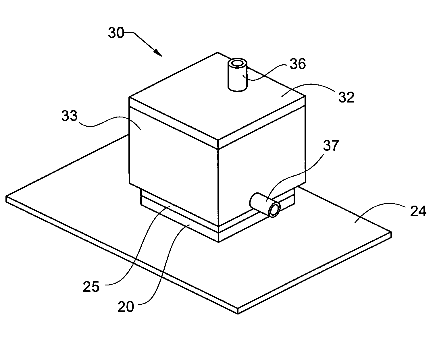
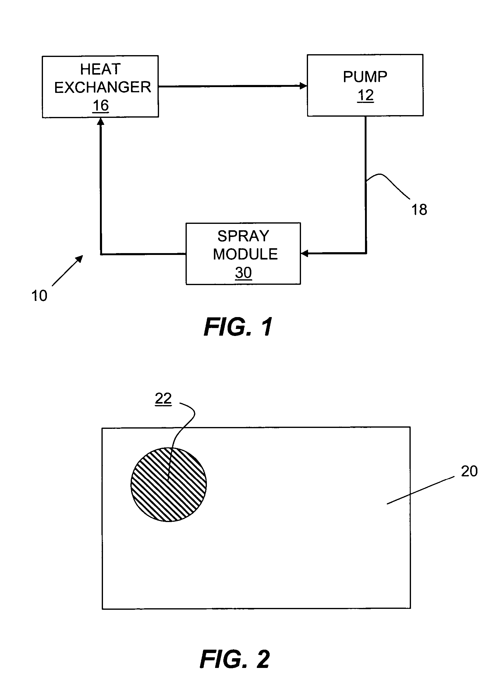
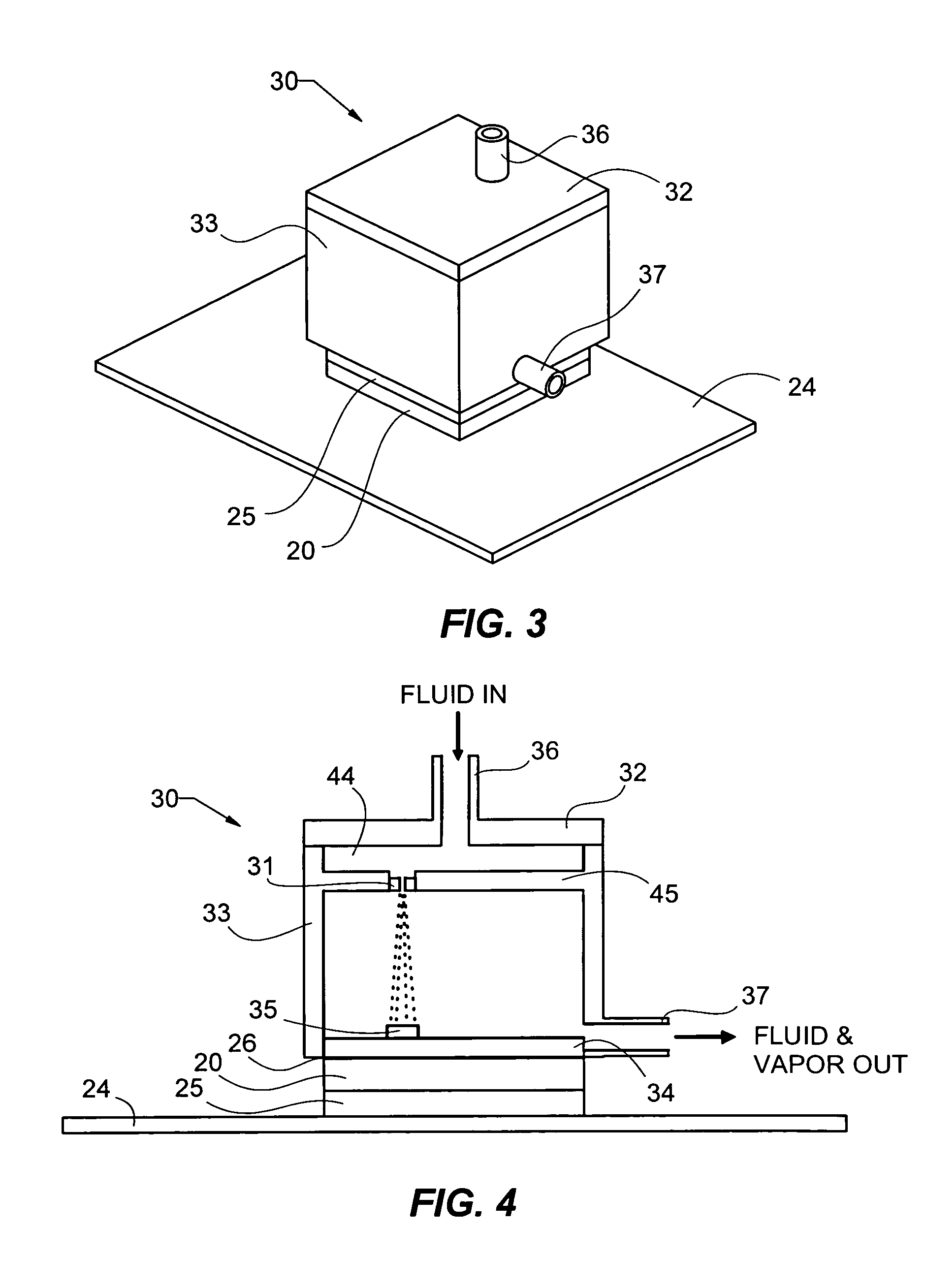
[0030]Now referring to FIG. 1, a closed loop two-phase spray cooling system 10 is shown. A liquid coolant (not shown) is pressurized by a pump 12. Preferably pump 12 is powered through the use of a direct current ...


PUM


Abstract

The present invention is a coldplate hotspot spray cooling system that cools an electronic component creating a varying amount of heat across its surfaces. Liquid coolant is dispensed upon a spray pin protruding from a base wherein the liquid creates a very high heat absorbing evaporative thin film. The spray pin is located over an area of the chip that produces a large heat flux, typically referred to as a hotspot. The small size and isolation of the spray pin provides the ability to generate very large heat fluxes. Multiple spray pins are possible.

Description

STATEMENT REGARDING FEDERALLY SPONSORED RESEARCH OR DEVELOPMENT[0001]This invention was made with Government support under contract # F33615-03-M-2316 awarded by the Air Force Research Laboratory. The Government has certain rights in this invention.CROSS REFERENCE TO RELATED APPLICATIONS[0002]We hereby claim benefit under Title 35, United States Code, Section 120 of U.S. patent application Ser. No. 10 / 260,713 filed Sep. 27, 2002 entitled “Thermal Management System for Evaporative Spray Cooling”. This application is a continuation-in-part of the Ser. No. 10 / 260,713 application. The Ser. No. 10 / 260,713 application is currently pending. The Ser. No. 10 / 260,713 application is hereby incorporated by reference into this application.BACKGROUND[0003]1. Field of the Invention[0004]The present invention relates generally to spray cooling thermal management systems and more specifically it relates to a coldplate spray cooling system that provides high heat evaporative cooling of electronic com...

Claims


Application Information

Patent Timeline
Patent Type & Authority Patents(United States)
IPC IPC(8): F28D5/00H01L23/433H01L23/473
CPCF28D5/00H01L23/4336H01L23/4735H01L2224/16H01L2924/3011
Inventor TILTON, CHARLES LWEIR, THOMAS DKNIGHT, PAUL A
Owner PARKER INTANGIBLES LLC
Why Eureka
Try Eureka